Quick Reference
Install
Guide
Remote Start
with
Keyless Entry
Model4105
Wiring Connections
Remote
stort,
6-pin
connector
OUTPU
T TO PR
IM
AR
Y IG
NITI
ON C
IR
CU
IT
OU
T
PUT
TO
STA
R
TE
R
CIRCUIT
OU
T
PUT
TO
ACCESSORY
CIRCUIT
(+)
(30A)
HIGH
CURRENT
12V
INPUT
OUTPUT
TO
SECON
D
IGNITION
/ACCESSO
RY
CIRCUIT
(+)
(30A)
HIGH
CURRENT
12V
INPUT
Remote
Start
harness,
5-pin
connector
Important:
NEVER
connect o
200m
A
low
cu
rr
e
nt
output dir
ed
ly to a motor or high
current device
W ITHOUT a
re
l
ay
.
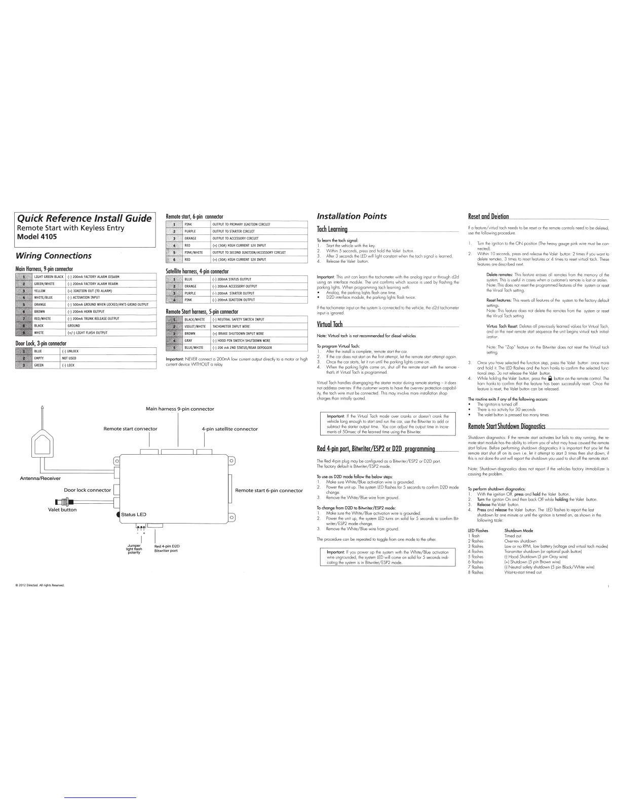
Main
harness
9-pin
connector
Remote
start
connector
i-
pin
satellite
connector
Antenna/Receiver
Door
lock
connector
Valet
button
ti~h~fra
8
;h
polarity
C
2012
Di
rected.
All
rights Reserved.
I
Red 4-
pin
020
Bitwriter
port
Remote
start
6-pin
connector
0
Installation Points
~mill
~
--------------------
To
learn
the
tach
signal
:
I
Start
the
vehi
cle
with
the
k
ey
.
2.
Within 5
seconds,
press
and hold
the
Valet
button.
3. After 3 seconds t
he
LED
will lig
ht
constant w
he
n the tach signal
is
learned
4
Re
lease
the
Va
l
et
button
Important:
This
unit can learn
the
tachome
te
r with
the
analog input or through
d2d
us
ing an interface module.
The
unit confi r
ms
whi
ch
so
ur
ce
is
used
by flashing
the
parking
li
ght
s.
When p
ro
gramming ta
ch
learning with:
Analog,
the
parking lights flash one t
im
e.
D2D interface module,
the
parking lights
flash
twice.
If
the
tachometer input
on
the
system
is
connected to
the
veh
icle, t
he
d2d
tachometer
input
is
ignored.
Virtuol
loch
Note: Virtual tach
is
not recommended for diesel vehicles
To
program
Virtual
Tach
:
1
Aher t
he
install
is
complete, remote start
the
car.
2.
If
the
cor does not
start
on
the
f
irs
t a
tt
empt, let
the
remote start attempt
aga
in
3.
Once
the
cor
star
ts
,
let
it
run
un
til
the
parking lights come
on
4.
When
the
parking lights come on,
shu
t off
the
re
mote
star
t
wi
th
the
remote·
that's
it
I
Vi
rtual
Tach
is
pr
og
rammed
Virtual
Tach
handles di
se
ng
aging
the
starter
mo
to
r during remote starting -
it
does
not address over-
rev.
If
the
cus
tomer wants to have the over-rev protection capabil-
ity,
the
tach wire
mus
t
be
connected.
This
may involve more installation shop
charges than
i
ni
ti
ally quoted.
Important:
If
the
Vi
rtu
al
Tach
mode over cranks
or
doesn't crank
the
vehicle long enough to start
and
run
the
cor,
use
t
he
Bitwriter
to
odd
or
subtract
the
starter
output ti
me
.
You
can
ad
jus
t
the
output
time
in incre-
ments
of 50msec of
the
learned time using
the
Bitwriter.
Re.d.A:pin
port,
Bitwriter/ESP2
or
020
programming
The
Red
4-pin plug may
be
configured as a Bitwriter/ESP2 or D2D port.
T
he
factory def
au
lt
is
Bitwriter/ESP2 mode.
To
use
as
020
mode follow
the
below
step
s:
1 fv\oke
sure
White/Blue
activation wire
is
grounded.
2. Power t
he
unit up.
The
system
LED
flashes
for
5 seconds to confirm D2D mode
change
3.
Remove
the
White/B
l
ue
wire
from
ground
To
chonge
from
D2D
to
Bitwriter/ESP2
mode
:
1 fv\o ke
sure
the
Wh
ite/Blue activation w i
re
is grounded.
2. Power
the
unit
up,
th
e
sys
t
em
LED
turns
on solid for 5 seconds to conf
irm
Bi
t-
writer /ESP2
mode change.
3.
Remove
the
White/B
l
ue
wire
from
ground.
The
procedure con
be
repeated to toggle
from
one mode
to
the
other.
Important:
If
you power up
the
system
with
the
Whi
t
e/B
l
ue
activation
wi
re ungrounded,
the
system
L
ED
will come on solid for 5 seconds indi-
cating the
system
is
in Bitwriter/ESP2 mode
Reset
nod
Deletion_
·--
--
--------
If
a feature/virtual tach needs
to
be
rese
t or
the
remo
te controls need
to
be deleted,
use
th
e
fo
llowing procedure.
1.
Turn
the
ignition to
the
ON
position
IThe
heavy gouge pink wire
must
be
con-
nected).
Within
10
seconds,
press
and release
the
Valet
button: 2
times
if you want to
delete
remotes,
3
ti
mes
to
reset
features or 4
times
to
reset
virtual tach .
These
features ore described next
Delete remotes: T
his
feat
ure
erases all
remo
t
es
fr
om
the
memory of
the
system
.
Th
is is
useful
in
cases when a
customer
's
remote
is
lost or stolen.
No
te:
Th
is
does not
re
set
the
programmed features of t
he
system
or
reset
the
Vi
rt
ual
Tach
setting.
Reset
Features:
This
resets
all features
of
the
system
to
the
factory
de
fa
ult
settings.
No
te:
This
feature does not
de
lete
the
remo
t
es
from
the
sys
tem
or
reset
the
Virtual
Ta
ch
setting
Virtual
Tach
Reset:
Deletes all previously learned val
ues
for
Virtual
Tach,
and
on
the
next
rem
o
te
sta
rt sequence
the
unit begins virtual tach
in
itial-
izatio
n.
No
te:
The
''ZapN
feature
on
the Bitwriter does not
rese
t
th
e Virtual tach
setting .
Once you hove selected
the
function
step,
press
the
Valet button once more
and hold
it.
The
LED
flashes
and t
he
horn
honks
to
confirm
the
selected func-
ti
onal step. Do not
re
lease the Valet button
4.
Wh
ile holding the
Va
let button,
press
the
Q button on
the
remote control.
The
horn honks to confirm that
the
feature
has
been successfully
reset
. O n
ce
the
feature
is
rese
t,
the
Va
l
et
button can
be
released.
The
routine exits
if
any
of
the following occurs:
The
ignition
is
turned off
There
is
no activity
for
30
seconds
The
valet button
is
pressed too many
times
Remote
Start
ShutdowlllliagmnoUJst
....
ics,____
____________
_
Shutdown diagnost
ics
:
If
the
re
mote
start
activates but fails
to
stay running,
the
re-
mo
te start modu
le
has
t
he
ability to
in
form
you
of
what may have caused
the
remote
sta
rt
failure. Before performing shutdown diagnostics il
is
impor
ta
nt
th
at you let
the
remote start
shut
off on
its
own i.e. let
it
attempt
to
start
3
ti
mes
then
shu
t down, if
th
is
is not done t
he
un
it will report
the
shutdown you
us
ed to
shut
off
the
remote
star
t.
No
te: Shutdown diagnostics does not report if
the
vehicles factory immobilizer is
causing
the
problem.
To
perform shutdown diagnostics:
1.
With
the
ignition Off, press and hold
the
Valet
button.
2
Turn
the
ignition
On
and
then
bock
Off
while holding t
he
Valet button.
3
Release
t
he
Valet button.
4.
Press
and release the Valet button.
The
LED
flashes to report
the
last
shutdown
for
one minute or
until
th
e ignition
is
turne
d on, as shown in
the
following table:
LED
Flashes
I f
lash
2 flashes
3 flashes
4
flashes
5 flashes
6
flashes
7flashes
8 flashes
Shutdown
Mode
Timed out
Over-rev shutdown
Low
or no
RPM,
low
ba
tt
ery [voltage and virtual loch modes)
Transmitter shutdown
(or
optional
pus
h button)
1-)
Hood
Shutdown (5 pin
Gray
wire)
[+)
Shutdown
15
p
in
Brown wi
re
)
1-l
Ne
utral safety shutdown (5 pin
Black/White
wire)
Wait-to-start timed out