10 © 1998 Directed Electronics, Inc. Vista, CA
N438 7/98
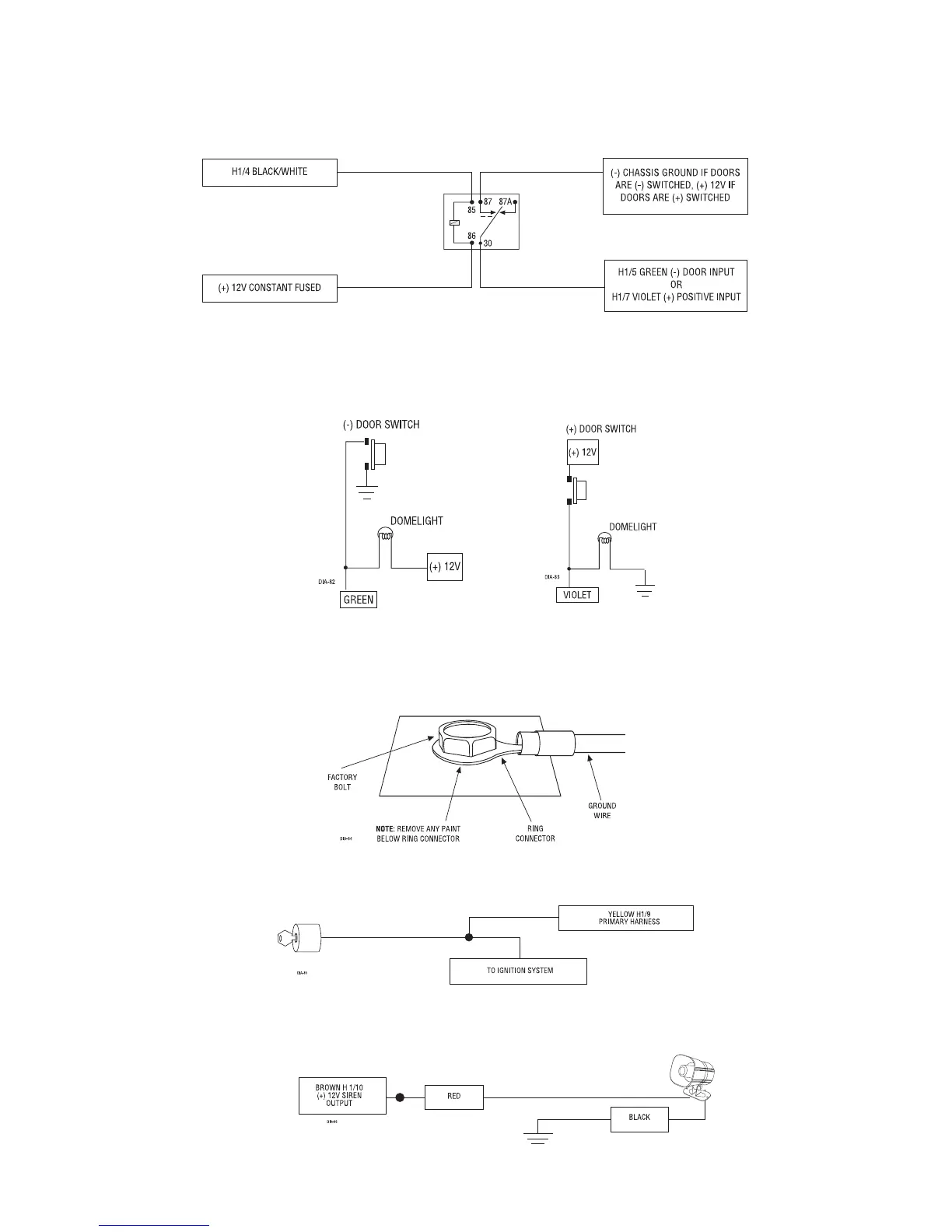
H1/4 BLACK/WHITE
(-) 200 mA domelight-supervision output: Connect this wire to the optional domelight super-
vision relay as shown below:
IMPORTANT: This output is only intended to drive a relay. It cannot be connected directly to the domelight
circuit, as the output cannot support the current draw of one or more light bulbs.
H1/5 GREEN
(-) door trigger or
H1/7 VIOLET
(+) door trigger input: If the door switch wire you found is (-) when the
door is open, connect the GREEN wire to it. If the door switch wire you found is (+) when the door is open, use the
VIOLET wire instead.
IMPORTANT! Test to make sure this wire "sees" all doors!
H1/6 BLUE
(-) instant trigger: This input will respond to a (-)input with an instant trigger. It is ideal for hood and trunk
pins and will report on zone one.
H1/8 BLACK
(-) chassis ground connection. Connect this wire to bare metal, preferably with a factory bolt rather
than your own screw (screws tend to either strip or loosen with time). We recommend grounding all your compo-
nents to the same point in the vehicle.
H1/9 YELLOW
(+) ignition input. Connect this wire to an ignition wire as described on page 5. This wire must show
+12V with the key in run position and during cranking. Take care to insure that this wire cannot be shorted to the
chassis at any point.
H1/10 BROWN
(+) siren output: Connect this to the red wire of the 514T Revenger
™
siren. Connect the black wire
of the siren to (-) chassis ground, preferably at the same point you grounded the control module’s H1/8 BLACK wire.