© 1998 Directed Electronics, Inc. Vista, CA
11 N438 7/98
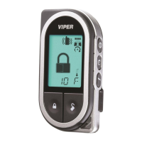
Green (-) Multiplex input: Inputs shorter than .8 seconds will trigger the Warn Away
®
response, while inputs longer
than .8 seconds will trigger full alarm sequence and report zone four. If installing an optional DEI
®
dual stage sen-
sor, connect to the green wire as shown below. The diagram below eliminates the need for diodes to isolate the
sensors, as well as providing a seperate zone for each sensor.
Diagram for adding optional DEI
®
dual stage sensor to GREEN wire (zone 4)
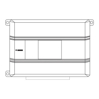
Blue (-) Multiplex input: Inputs shorter than .8 seconds will trigger the Warn Away
®
response, while inputs longer
than .8 seconds will trigger full alarm sequence and report zone two.
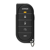
Red, Black: Red is (+)12V constant, black is (-) ground. Do not use these for anything besides the plug in shock
sensor.
H1/11 RED
(+)12V constant power input: Before connecting this wire, remove the supplied fuse. Connect to the
battery positive terminal or the constant 12V supply to the ignition switch as described on Page 5.
NOTE: Always use a fuse within 12 inches of the point you obtain (+)12V. Do not use the 15A fuse in the
harness for this purpose. This fuse protects the module itself.
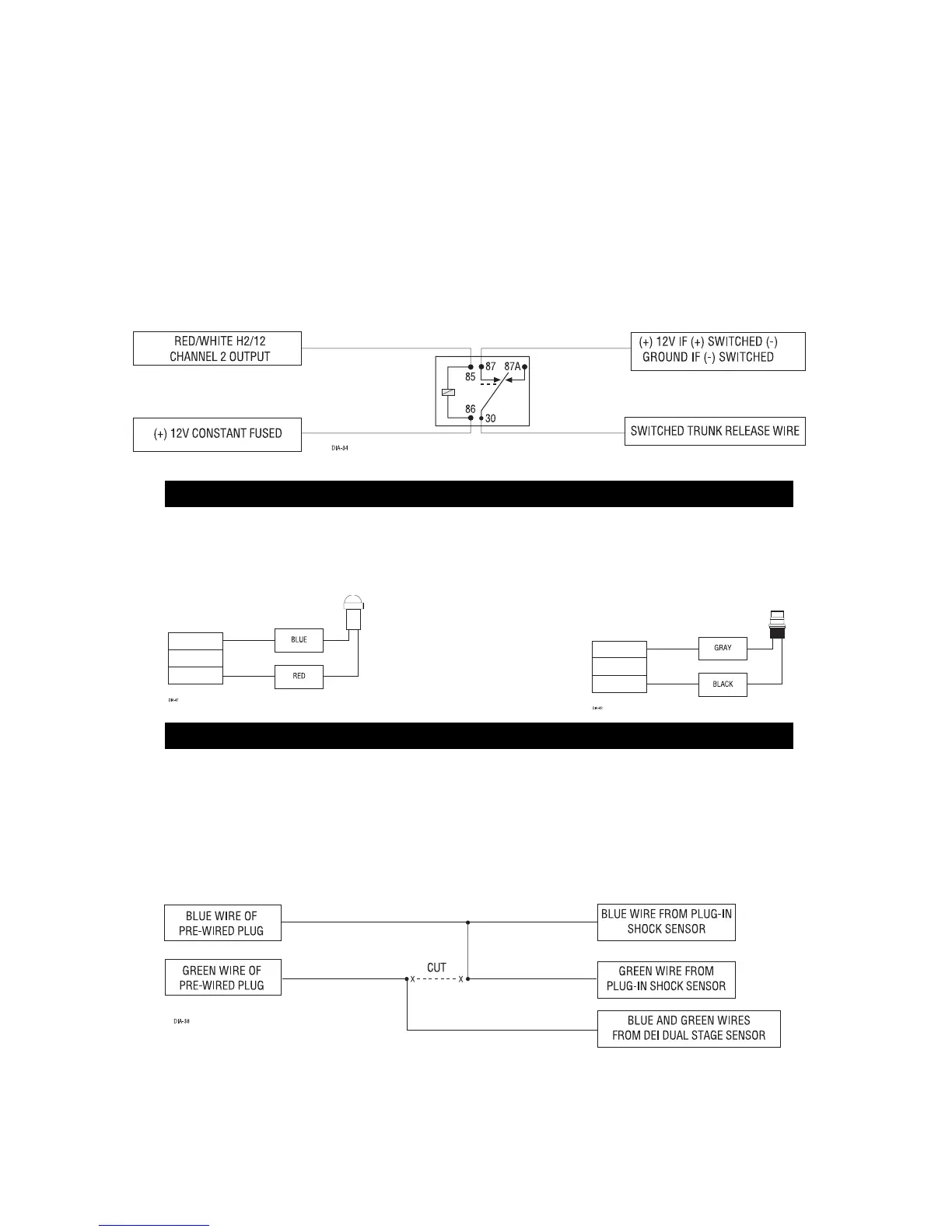
H1/12 RED/WHITE
channel 2, (-) output: When the system receives the code controlling channel, for longer than
1.5 seconds, the red/white will supply a (-) 200mA output as long as the transmission continues. This is often used
to operate a trunk/hatch release or other relay-driven function.
IMPORTANT! Never use this wire to drive anything but a relay or a low-current input! The transistorized
output can only supply 200 mA of current, connecting directly to a solenoid, motor, or other high-current
device will cause it to fail.
These plug into the module. The Status LED plugs into the small two-pin socket, while the Valet
®
/Program Switch
should be plugged into the larger blue two-pin connector. The Status LED fits in a 9/32" hole.
Status LED Valet
®
/Program Switch
FOUR-PIN SHOCK SENSOR HARNESS
LED AND VALET
®
/ PROGRAM SWITCH