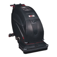
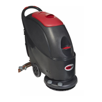
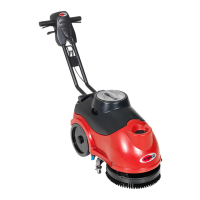
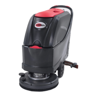
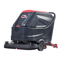
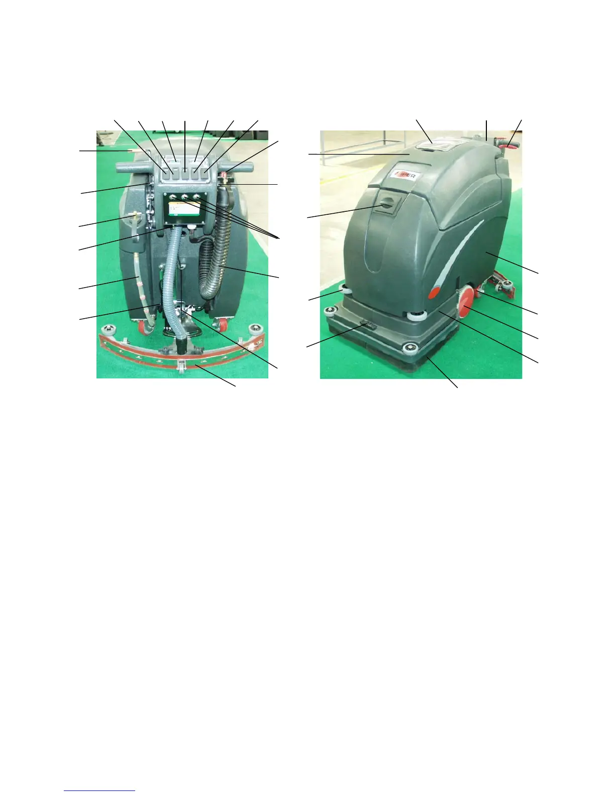
MACHINE COMPONENTS
1. Main power ON/OFF switch
2. Vacuum ON/OFF switch
3. Battery level meter
4. Brush ON/OFF switch
5. Brush pressure meter
6. Solution ON/OFF switch
7. Brush pressure UP/DOWN switch
8. Solution control knob
9. Speed control knob
10. Circuit breakers
11. Recovery tank drain hose
12. Squeegee adjustment nut & shaft
13. Squeegee assembly
14. Scrub head actuator
15. Solution tank level sight tube
16. Console adjustment levers
17. Rear solution fill
18. Reverse switch
19. Squeegee lift lever
20.
Co
ntrol housing
21. Operating triggers
22. Solution tank
23. Rear casters
24. Transport wheels
25. Scrub head
26. Scrub head skirt
27. Skirt housing latch
28. Protective rollers
29. Front solution fill
30. Recovery tank
31. Recovery tank lid
7
10
11
13
19
12
9
8
6 5 4 3 2 1
18
17
16
15
14
20 21
22
26
27
31
23
24
25
28
29
30
4
 Loading...