VISLINK
Flydrive 120-150 Antenna 13
lift the amplifier onto the roof rack next to the antenna base.
Fasten the inner HPA mounting bracket onto the main antenna base.
Fasten the outer clamp around the roof bar.
Fit the cross site waveguide between the HPA and feedarm base waveguide interface.
Care should be taken in operation that the flex/twist waveguide can run freely between
the amplifier and antenna. An antenna movement of between +90 and –180 degrees in
azimuth should not cause problems, but it may be necessary to either point the antenna
without the cross site waveguide fitted or move the vehicle for full 360 degrees azimuth
movement.
Select the deploy command from the front panel of the ACU. The Flydrive will deploy
automatically, calibrating the elevation, azimuth and polarisation axis on each deploy
sequence. Select the stow command from the front panel of the ACU. The Flydrive will
stow automatically.
To remove the roof rack feet from the antenna, remove the end cap completely from the
end cap housing and push the inner release latch in and pull the end cap housing out of
the roof bar.
3.3 MANUAL OPERATION
The antenna may be moved manually if there is a problem with the control circuit.
The azimuth axis is moved by inserting the manual drive a handle into the azimuth adjust
slot in the side of the antenna base and turning.
Apply power to the antenna using the main power cable. The elevation axis is moved by
releasing the brake using the switch on the main antenna cable interface panel and
inserting the manual drive handle into the elevation adjust slot in the side of the antenna
base and turning.
The polarisation axis is moved by rotating the rear section of the feedhorn.
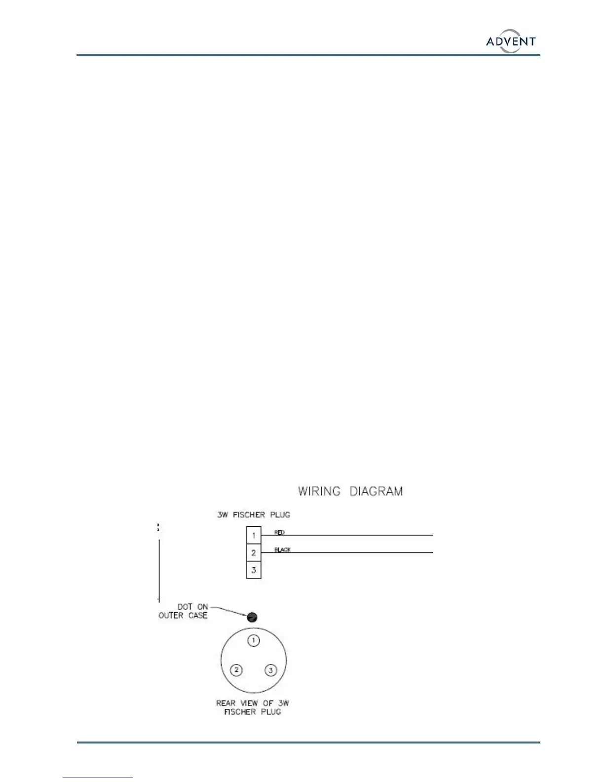
If AC power is not available a 12V DC input may be used to release the brakes. Insert
the supplied brake override DC input cable, apply a 12V DC battery and use the brake
release switch as with the AC input. The cable pin outs are shown below.