User Manual Focal Point
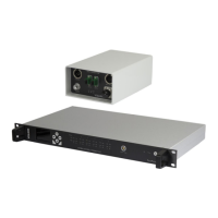
Operators Control Panel (OCP5) OCP5-ASSY-7XXX
Issue No: M Page: 44
Ref: FOCL-ASUM-8xxx Copyright © 2017 Vislink plc
Data output from the OCP5 to the Camera Control Interface Unit may be configured in
either of the following ways:
OCP I/F connector - this is the normal method which also allows the OCP5 to derive
its power from the Camera Control Interface Unit (see Section 6.2.1)
Data in/out connector - this method is used where longer lengths of cable are used,
up to the limits for RS485 (see Section 6.2.2)
Use the Data in/out connector to handle the Data input from the camera to the OCP5.
NOTE: When used for return data to the Vislink OCP5, set the User Data port on the
microwave video link (transmitter and the receiver) to a baud rate of 115,200.
Table 6-1 OCP5 Control Functions
You can assign a favorite function to the OPT button. Doing this makes it is instantly
available from the OCP5 front panel.