™
Page 24 of 59
3 Using the vLoc3 Series Receivers
When taking a depth reading the signal current value will also be displayed. This feature is useful for confirming that the
detected signal is radiating from the correct line. If the signal is bleeding o onto other services these signals will generally be
less than that of the originating signal. However, care should be taken as the signal current will gradually reduce over the length
of the line. Watching for a sudden drop in current over distance should indicate that either:
1. There is a ground fault on the line which is a shunting signal to ground.
2. There is a Tee off from the mainline.
3. The operator has migrated from the connected line to a line with some signal bled across from the mainline.
3.8 Distorted Fields
Always be aware that you are locating the signals radiating from the buried line. These radiated elds can be distorted by other
lines or electromagnetic signals from buried lines. Metallic structures like crash barriers or wire mesh fences can also help to
distort signals.
vLoc3 series receivers can detect the presence of possible distortion. The Vector screen has a circle drawn around the target
line, which increases in size in the presence of possible distortion. The Plan view screen has “Tram” lines on either side of the
calculated position, which moves further from the line as possible distortion is detected.
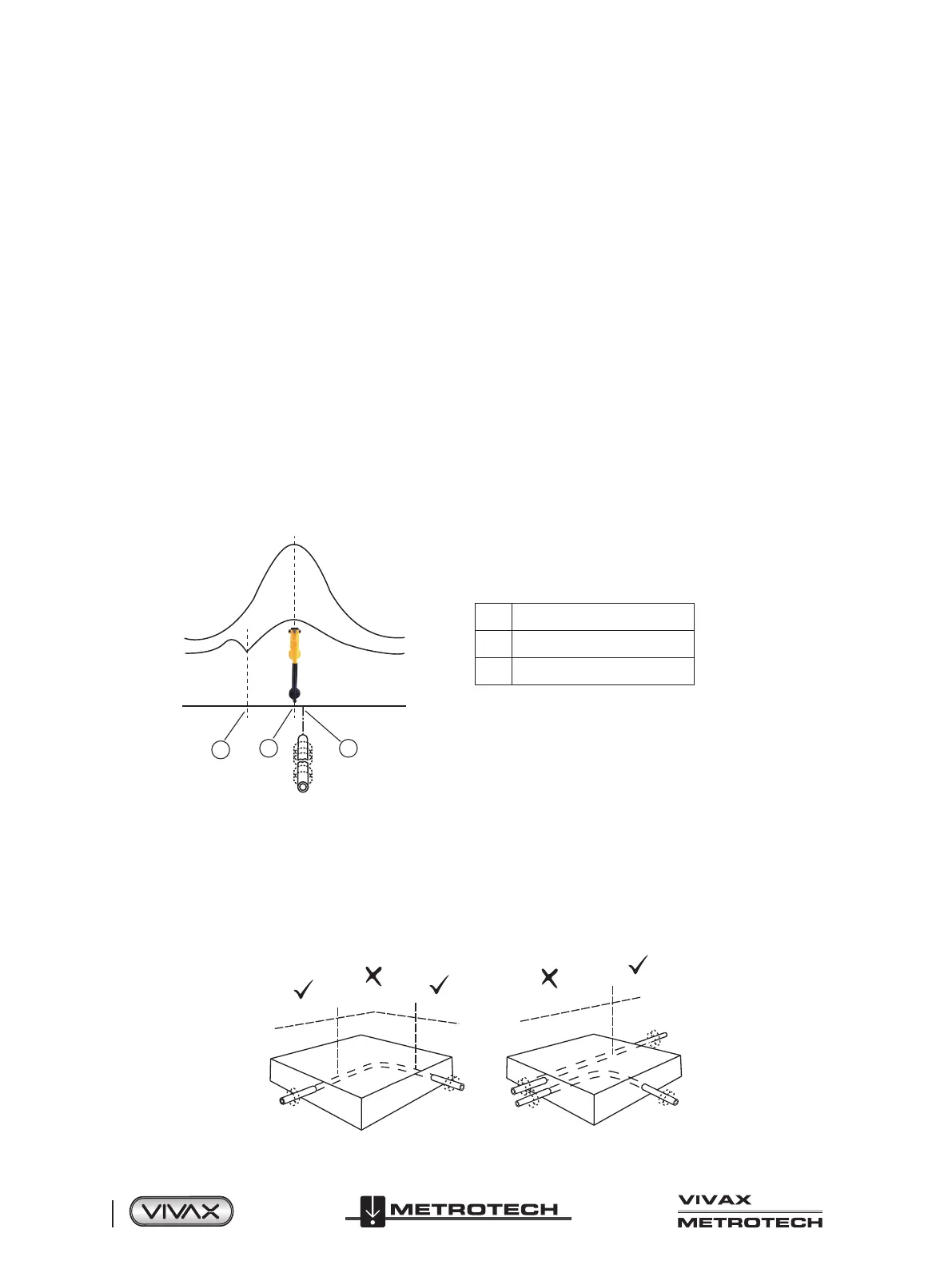
However, when using the traditional screen the risk of an inaccurate location can be reduced further by doing the following:
• Check to see if other radiated fields are distorting the signal. Locate the cable, first in the Peak mode and then in the Null
mode or use the left/right arrows. The two locations should indicate that the cable is in the same place. If they do not, the
signal field is distorted, and the depth and current measurement may be inaccurate.
2
1
3
1 Null Position
2 True Position
3 Peak Position
When the Peak and Null positions do not line up
• Measure the buried line's depth by pressing the “i ” pushbutton briefly to measure depth and current. The depth should be
approximately in line with the “as-built” plans available. If no plans are available, logic would still help assess the situation
(for instance, if you are looking for a shallow CCTV distribution cable and the depth indicated is 5ft (1.5m), it should raise a
concern).
• Take a depth reading on the ground and then raise the locator approximately 1ft or 0.25m and repeat the depth measurement.
The depth should increase by this amount. If not, treat the information with caution.
• A depth reading on congested areas or close to bends or tees may be inaccurate due to distorted fields.
d
d
d
d
d
 Loading...