EN - 6
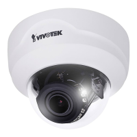
1
2
RJ45 Cable Dimension (unit: mm)
2. Strip part of the sheath from the
Ethernet cable.
1. Drill a hole on the rubber seal
plug and insert an Ethernet cable
through the opening.
Rubber Seal
Plug
Assembling Steps
Recommended cable gauge: 24AWG (0.51 mm)
Connecting RJ45 Ethernet Cable
4
3
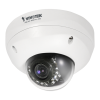
o
O
g
B
b
G
br
BR
1
2
3
4
5
6
7
8
o: white/orange stripe
O: orange solid
g: white/green stripe
B: blue solid
b: white/blue stripe
G: green solid
br: white/brown stripe
BR: brown solid
3. You will need an RJ45 crimping tool to
attach the Ethernet wires to a connector.
When done, connect the cable to the
camera’s Ethernet RJ45 socket.
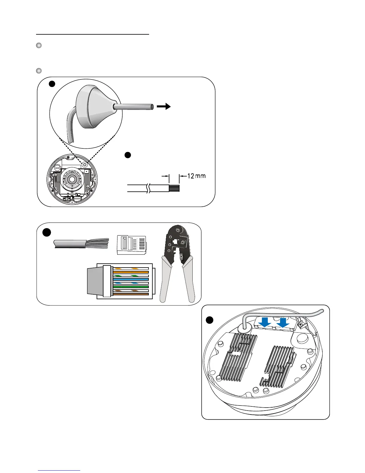
4. Press the Ethernet cable into the routing path at
the bottom of the camera so that the cable will not
get in the way when the metal mounting plate is
attached.
 Loading...