EN - 8
POW
ER
C
O
LL
I
S
ION
L
I
N
K
RE
CEIVE
PARTITIO
N
1
2
3
4
5
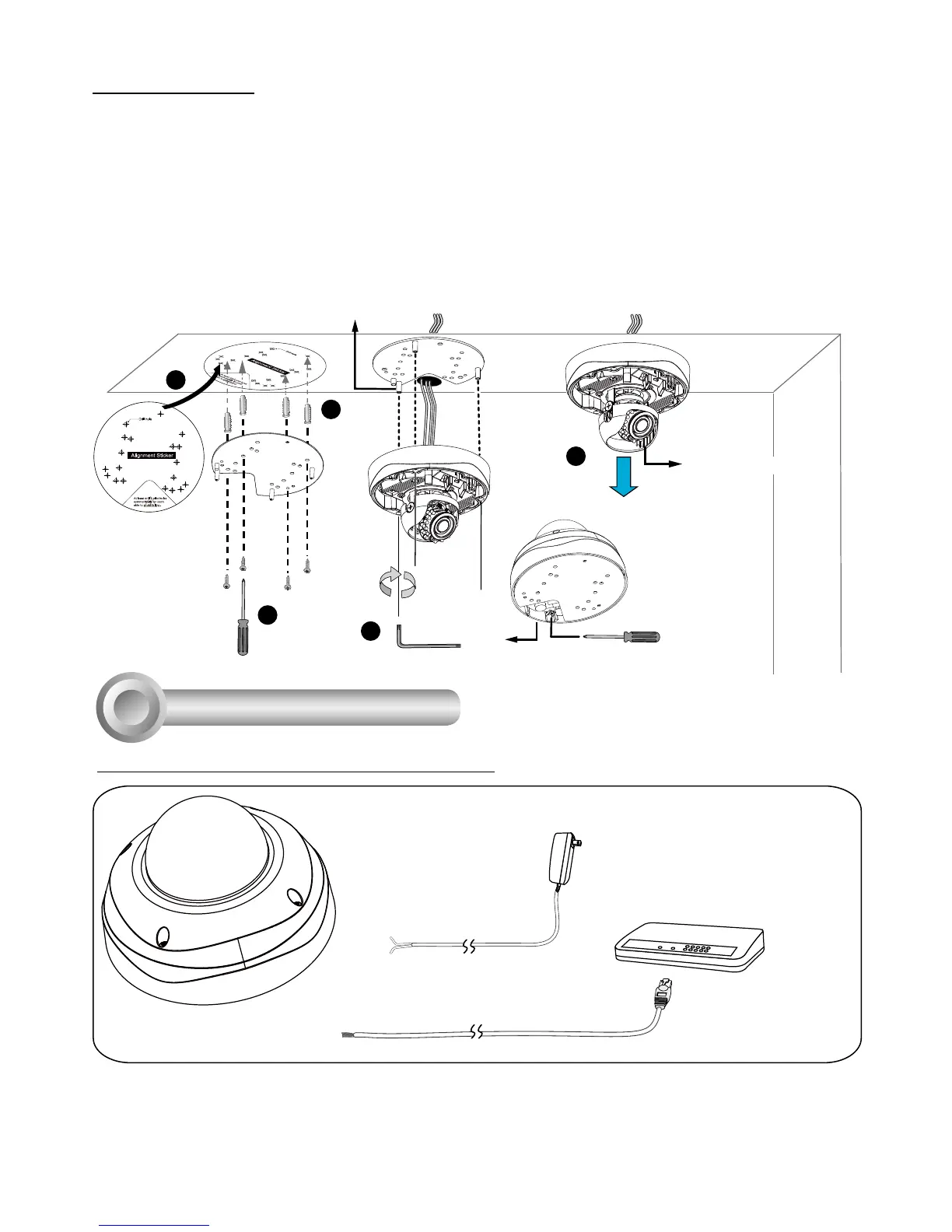
Network Deployment
4
1. Connect RJ45 Ethernet cable to a switch.
Use a Category 5 Cross Cable when your
network camera is directly connected to PC.
2. Connect the AC cables from the terminal
block as an alternate power source. The IO
cables are user-supplied.
Ethernet
Non-PoE Switch
Pin 1
Pin 2
AC 24V±10%
Black
Red
General Connection (without PoE)
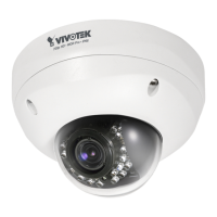
Ceiling mount
1. Attach the supplied alignment sticker to the ceiling.
2. Using the circle marks on the sticker, drill at least 2 pilot holes symmetrically on each side into the
ceiling. Then hammer the four supplied plastic anchors into the holes.
3. Through three or four holes on the mounting plate, insert the supplied screws into the corresponding
holes and secure the mounting plate with a screwdriver.
4. Feed the cables through the triangular cutout A or side opening B. If you want to use hole B, remove
the side cover using a screwdriver. Secure the camera base to the mounting plate with three supplied
screws.
5. Remove the black cover.
1
A
B
5
2
3
4
Black Cover
 Loading...