VIVOTEK
10 - User's Manual
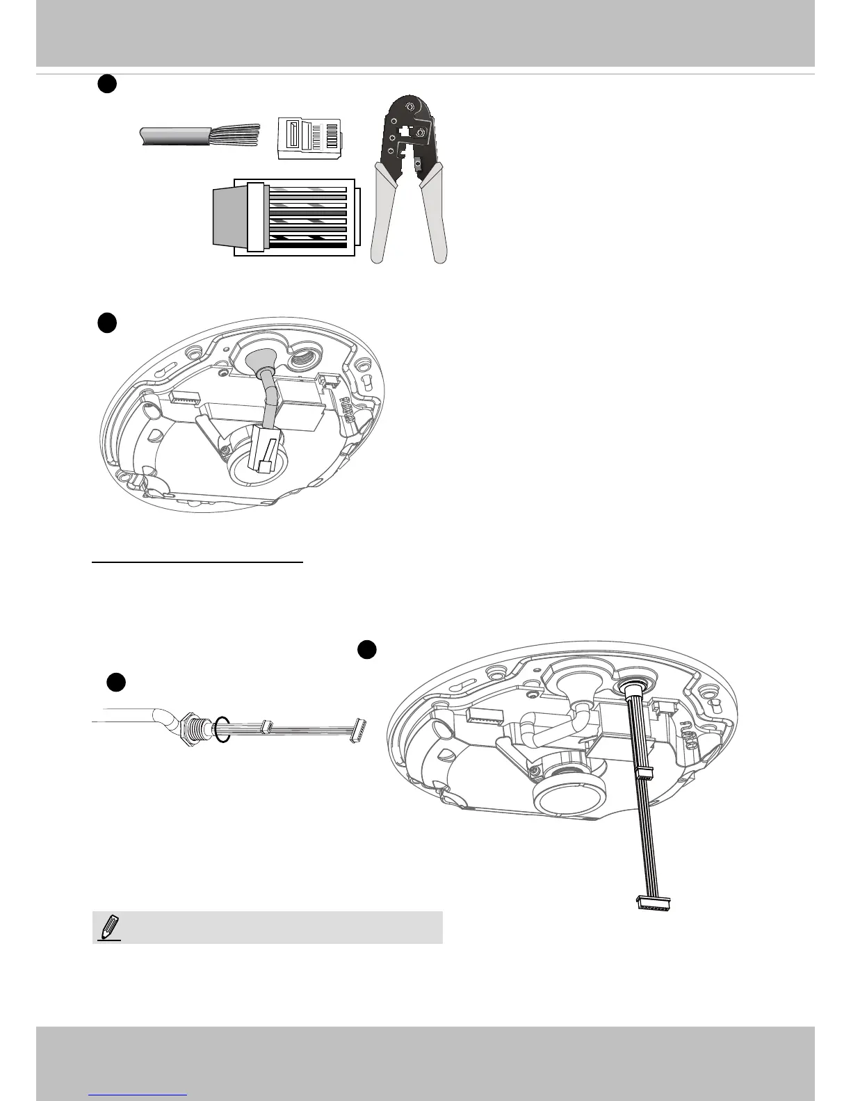
3. You will need an RJ45 crimping tool to
attach the Ethernet wires to a connector.
When done, connect the cable to the
camera’s Ethernet RJ45 socket.
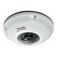
Connecting DC Power Cable
o
O
g
B
b
G
br
BR
1
2
3
4
5
6
7
8
3
4
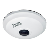
4. Feed the Ethernet cable from the bottom of the
camera and through the hole. Attach the rubber
seal plug for water proong.
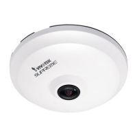
1. Add the supplied rubber washer to the cable as shown in the picture.
2. Feed the cable from the bottom of the camera and tighten the plastic base for waterproong.
o: white/orange stripe
O: orange solid
g: white/green stripe
B: blue solid
b: white/blue stripe
G: green solid
br: white/brown stripe
BR: brown solid
1
2
Connect the supplied power & IO cables if your
switch does not support PoE.
NOTE: