Network Deployment
Setup the Network Camera over the Internet
This section explains how to congure the Network Camera to Internet connection�
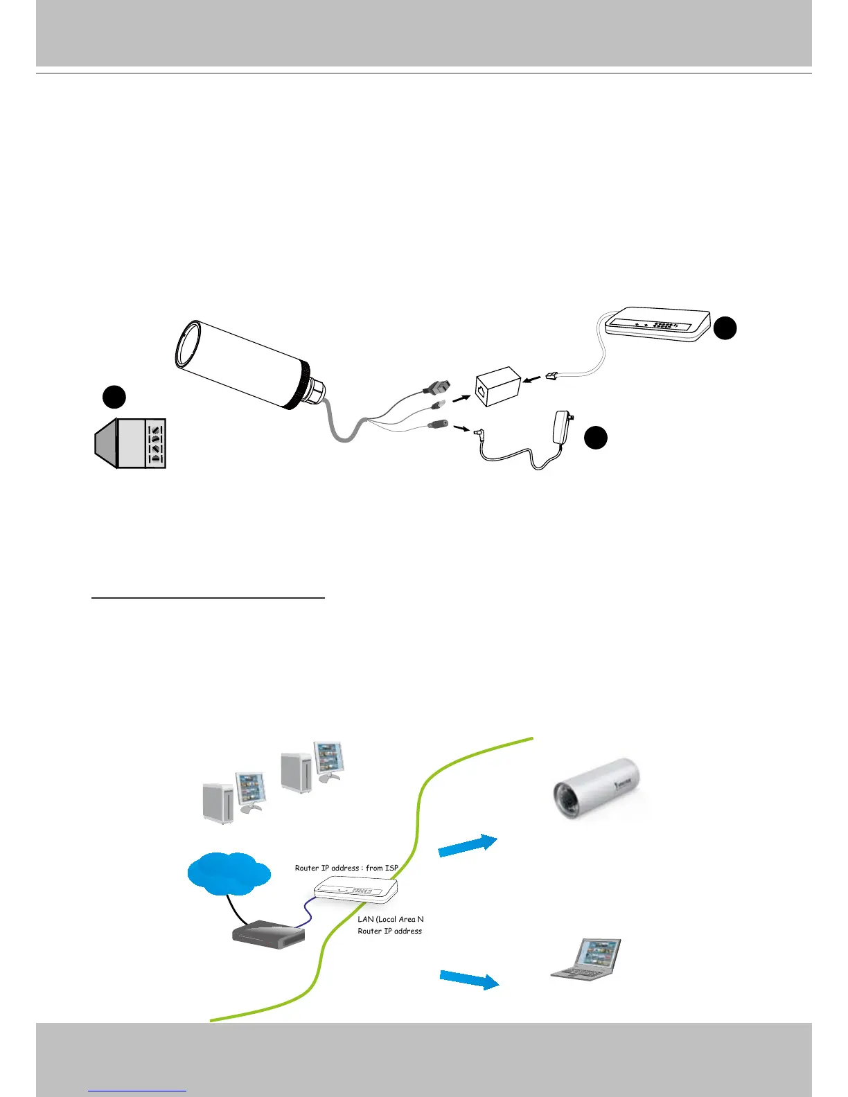
1. If you have external devices such as sensors and alarms, make the connection from the
general I/O terminal block�
2� Use the supplied RJ45 female/female coupler to connect the Network Camera to a switch.
Use Category 5 Cross Cable when Network Camera is directly connected to PC�
3� Connect the power cable from the Network Camera to a power outlet�
There are several ways to set up the Network Camera over the Internet� The rst way is to set
up the Network Camera behind a router� The second way is to utilize a static IP� The third way is
to use PPPoE�
Internet connection via a router
Before setting up the Network Camera over the Internet, make sure you have a router and follow
the steps below�
1� Connect your Network Camera behind a router, the Internet environment is illustrated below�
Regarding how to obtain your IP address, please refer to Software installation on page 10 for
details�
IP address : 192.168.0.3
Subnet mask : 255.255.255.0
Default router : 192.168.0.1
IP address : 192.168.0.2
Subnet mask : 255.255.255.0
Default router : 192.168.0.1
LAN (Local Area Network)
Router IP address : 192.168.0.1
WAN (Wide Area Network )
Router IP address : from ISP
Cable or DSL Modem
POW ER
COLLISION
LINK
RECEI VE
PARTITI ON
1
2
3
4
5
Internet