VIVOTEK
User's Manual - 9
GND
DO2-
DO1-
DO+
GND
D13
D12
D11
P
O
W
E
R
C
O
L
L
I
S
IO
N
L
I
N
K
RE
CEIVE
PA
RT
ITI
O
N
1
2
3
4
5
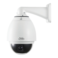
1. If you have external devices such as sensors and alarms, connect them to the general I/O
terminal block.
2. Use the supplied RJ45 female/female coupler
to connect the Network Camera to a switch.
Use Category 5 Cross Cable when Network
Camera is directly connected to a PC.
(AC 24V 3.5A) Power Adapter
POWER
COLLISION
LINK
RECEIVE
PARTITION
1
2
3
4
5
GND
DO2-
DO1-
DO+
GND
D13
D12
D11
When using a non-PoE switch
Use a PoE Plus power injector to connect between the Network Camera and a non-PoE switch.
Non-PoE Switch
PoE Plus Power Injector
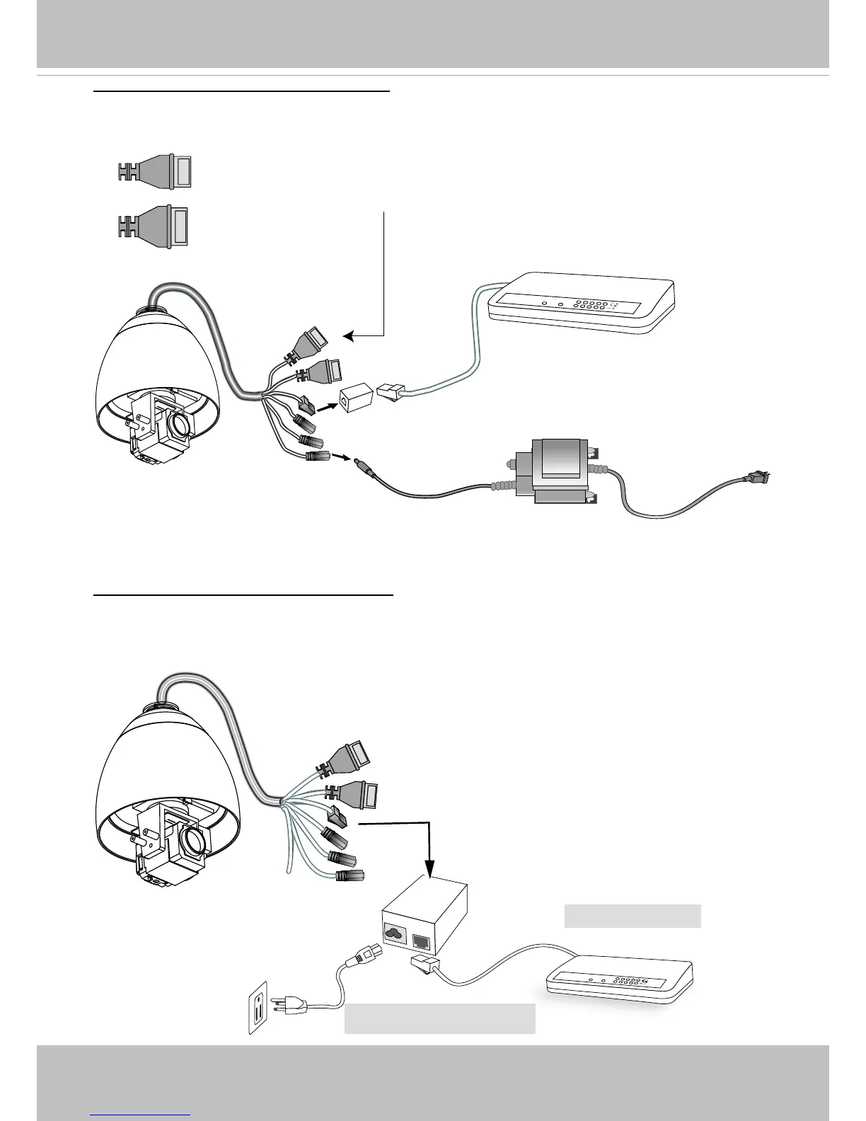
3. Connect the power cable from the
Network Camera to a power outlet.
Power over Ethernet (PoE 802.3at)
General Connection (without PoE)
GND: Ground
DO2: Digital Output 2
DO1: Digital Output 1
DO+: Digital Outupt (DC12V)
GND: Ground
DI3: Digital Input 3
DI2: Digital Input 2
DI1: Digital Input 1