VIVOTEK
User's Manual - 17
Network Deployment
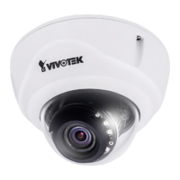
General Connection (PoE)
When using a PoE-enabled switch
The Network Camera is PoE-compliant, allowing transmission of power and data via a sin-
gle Ethernet cable. Follow the below illustration to connect the Network Camera to a PoE-
enabled switch via Ethernet cable.
PoE Switch
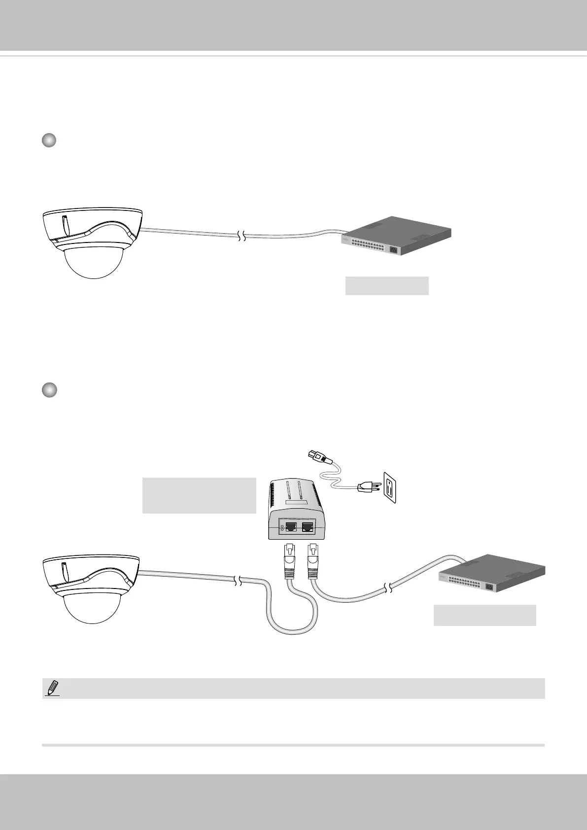
When using a non-PoE switch
Use a PoE power injector (optional) to connect between the Network Camera and a non-
PoE switch.
Non-PoE Switch
PoE Power Injector
(optional)
NOTE:
1. The camera is only to be connected to PoE networks without routing to outside plants.
2. For PoE connection, use only UL listed I.T.E. with PoE output.
802.3af
 Loading...