31
Maintenance
Maintenance
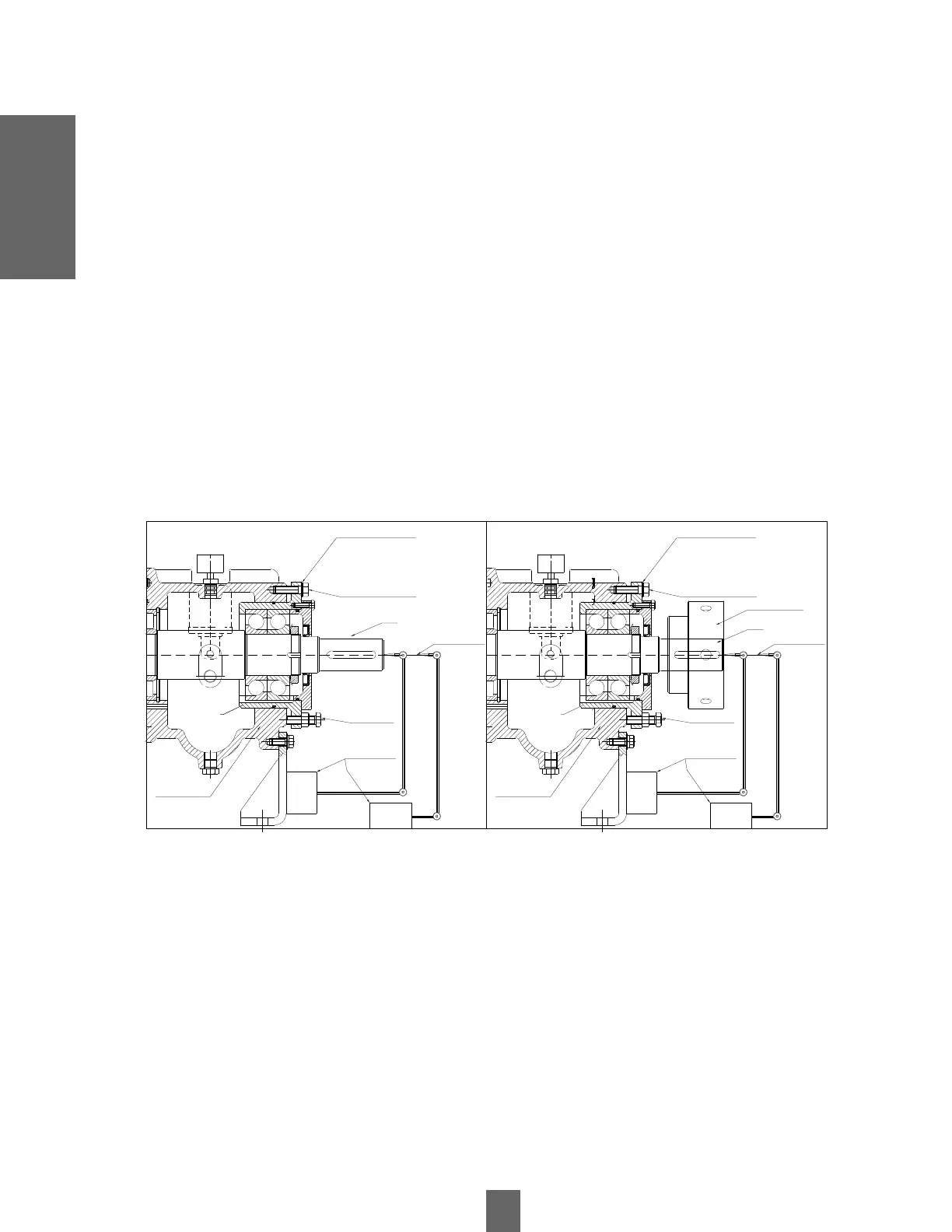
7.11.1 Impeller Backlash Adjustment Using Magnetic Base Dial Gauge
• Remove the grid from the plug cover.
• Remove the flexible body from the coupling core.
• Loosen the shaft adjusting bolts (fig.25) until a clearance of about 5 to 8 mm is achieved.
• Tighten the bearing housing - motor bracket bolts (fig. 24), until the impeller stops in the pump casing. This is
checked by turning the shaft by hand until friction is felt.
• Install the magnetic base dial indicator, with its base on the bearing housing leg and its measuring end on the shaft
end or on the ground surface of the coupling hub.
• Loosen the bearing housing - motor bracket bolts (fig.25) until a clearance of about 5 to 8 mm is achieved.
• Tighten the shaft adjusting bolts (fig.25) until the dial indicator registers a 0.4mm advance.
• Tighten the bearing housing - motor bracket bolts (fig.25) to the stop, checking that no changes are registered on
the dial indicator.
• Remove the magnetic base dial indicator. Install the flexible body of the coupling pin. Install the core cover grid.
Bearing
housing
Bearing
housing
Bearing Housing -
Bearing Body Bolts
Shaft
adjustment
bolts
Graduated Laminates
Axis
Bearing body
Clock Needle
Comparator
Base Reloj
Comparador
Shaft
adjustment
bolts
Graduated Laminates
Axis
Bearing body
Clock Needle
Comparator
Base Reloj
Comparador
Machon dough
$% re
Bearing Housing -
Bearing Body Bolts
 Loading...