32
Maintenance
Maintenance
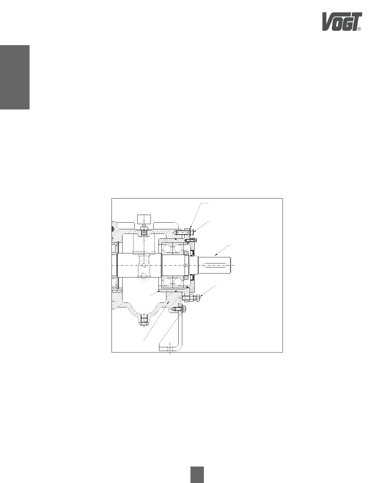
7.11.2 Impeller Clearance Adjustment Using Graduated Blades
• Remove the grid from the plug cover.
• Remove the flexible body from the coupling hub.
• Loosen the shaft adjusting bolts (fig.26) until a clearance of about 5 to 8 mm is achieved.
• Tighten the bearing housing - bearing housing bolts (fig.26), until the impeller stops in the pump housing. This is
checked by turning the shaft by hand until friction is felt.
• Loosen the bolts of the bearing housing. - Remove the bearing housing bolts (fig.26), until a clearance greater than
0.5mm is achieved.
• Place a calibrated sheet with a thickness of 0.4mm under the head of the bearing housing - bearing body bolt
(fig.26).
• Screw the bearing housing - bearing body bolts (fig.26), until it rubs against the calibrated sheet (0.4mm).
• Remove the calibrated sheet.
• Tighten the shaft adjustment bolts, until the bearing housing touches the bearing housing - bearing body bolts
(fig.26), until it rubs against the calibrated sheet (0.4mm). -Remove the bearing body (fig.26).
• Tighten the bearing housing - bearing body bolts (fig.26).
• Install the flexible coupling core body. Install the core cover grid.
Bearing housing
Case Bolts
Bearing Holder -
Bearing Body
Shaft Adjustment Bolts
Graduated Laminates
Axis
Bearing body
$% re-
 Loading...