7 Connections
Make sure the power switch is off before attempting to make
any input or output connections.
By using good quality input and speaker cables, the likeli-
hood of erratic signal behaviour is reduced to a minimum.
Whether you make them or buy them, look for good quality
wires, connectors and soldering techniques.
7.1 Signal grounding
There is no ground switch or terminal on the Bias Series am-
plifiers. All shield terminals of input connections are directly
connected to the chassis. This means that the unit’s signal
grounding system is automatic. In order to limit hum and/
or interference entering the signal path, use balanced input
connections.
In the interests of safety, the unit MUST always operate with
electrical safety earth connected to the chassis via the dedi-
cated wire in the 3-wire cable (ref. Chapter 6 : 3.AC m ains
supply). Never disconnect the ground pin on the AC mains
power cord.
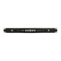
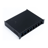
7.2 Analog input
Analog input is provided by means of two Neutrik XLR
connectors in Bias V3 or a couple of XLR/jack hybrid combo
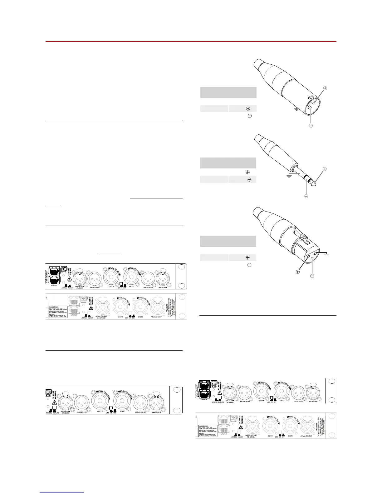
connectors in Bias V9 amplifiers. Signal polarity for XLR and
TRS plugs is shown in FIGURE 8.
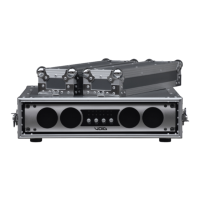
7.3 Analog line output
Line out is provided in Bias V3 via a couple of XLR connectors
on the rear panel. In DSP equipped models, the output
signal is pre-DSP, being a replica of the input signal.
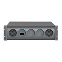
7.4 Digital Input
On DSP equipped models, the XLR input for channel 2 can
switch to an AES3 digital input. The AES3/analog push-
button located nearby the channel 2 XLR input connector
toggles the XLR between analog and digital input.
In AES3 mode
• the channel 2 analog line out is off;
• the channel 1 analog input can be used as redundant
input if the digital input fails.
FIGURE 8: Signal polarity in balanced connections;
A) XLR-M plug; B) TRS jack; C) XLR-F plug.
Analog input
XLR-M pinout
Pin 1 GND
Pin 2
HOT
Pin 3
COLD
Analog input
TRS Jack pinout
Tip
HOT
Ring
COLD
Sleeve GND
A
C
B
HOT
HOT
1
S
2
R
3
T
COLD
COLD
GND
GND
Analog line output
XLR-F pinout
Pin 1 GND
Pin 2
HOT
Pin 3
COLD
HOT
1
2
3
COLD
GND
FIGURE 9: Analog input in Bias V3 (top) and Bias V9 (bottom).
FIGURE 11: Digital input in Bias V3 (top) and Bias V9 (bottom).
FIGURE 10: Analog line output in Bias V3.