9.10.3 Cross limit
In case of power limiting of only one channel (ref. Chapter 9 : 6.
Amplifier settings: Clip limiter CH1/CH2), the gain reduction
on one channel is mirrored to the other channel in order to
maintain consistent signal levels. This is useful in two ways
speakers where the limitation of one channel alone leads to
an unbalanced sound. This function can be turned on or off.
9.10.4 Sound speed (m/s)
This menu allow the user to set the sound velocity used for
time to distance conversions throughout the local interface. It
can be set from 320 m/s to 360 m/s.
9.11 DSP Settings: Channel settings
All of the following settings are available for both channel 1
and channel 2. In all the following menus and submenus, the
channel number whose properties are being edited is shown
in the top right hand corner of the menu. If a specific parameter
affects both channels, the top right hand corner will report this
as “1+2”.
9.11.1 E Q s
This menu gives access to the parametric output equalizer
interface. This menu lists the 16 parametric filters one by one.
The current selected filter number is shown on the left of the
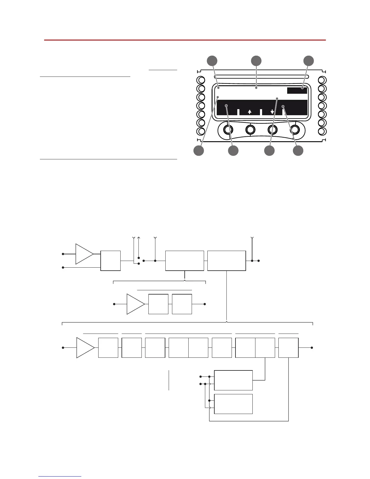
PEQ #12 Peak
CH1
back
edit
Freq=21205Hz G=+12dB
BW=0.63oct Q=21.3
FIGURE 27: EQ settings: 1) Filter number; 2) Filter type;
3) Channel; 4) Frequency; 5) Bandwidth; 6) Gain; 7) Q.
1
6
2 3
5 74
Load power
estimation
INPUT
PROCESSING
INPUT
SELECT
CHANNEL
PROCESSING
DAMPING
CONTROL
TruePOWER
LIMITER
PEAK
LIMITER
POLARITY
Hi-PASS
FILTER
Lo-PASS
FILTER
CHANNEL
DELAY
FIR EQ
Output current
Output voltage
output
monitor
16 bands parametric EQ Custom FIR Enhanced limiter
Cable loss
compensationIIR and FIR linear phase crossover
CHANNEL
PEQ16
Load impedance
estimation
GAIN
MAIN
DELAY
INPUT EQGAIN
GAIN
AES3
Analog
To/from
other channel
SigGen SigGen
To output stage
Raised cosine lters EQ
FIGURE 28: DSP processing diagram.