7.6.2 Internal signal path polarity
In order to increase the power’s supply energy storage ef-
ficiency, signals coming from each channel pairs are polarity
reversed, one with respect to the other within the pair, when
entering the amplifier. This ensures a symmetrical use of the
voltage rails: if, for example, both channels’ 1 and 2 input
signals are going through a peak at the same time, channel 1’s
energy will come from the positive voltage rails while channel
2, whose polarity is reversed with respect to channel 1, will
be fed energy from the negative voltage rails. In this manner,
the power supply will work symmetrically, with one channel
catered by the positive rails and the other by the symmetrical
negative rails. Channel 2’s signal will be polarity reversed once
more at the output connectors to ensure that both channels
output with the same polarity as their corresponding input
signals.
7.7 V Ext
The V Ext terminal is used to remotely manage the DSP in Bias
Series DSP amplifier and enable remote on/off.
Bias Series provided with a AESOP board have a dedicated 2
pin Phoenix connector MCV 1,5/ 2-G-3,81 - 1803426 located
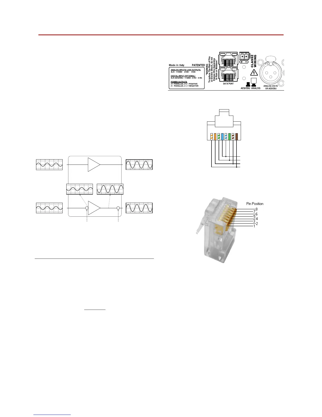
near the rear Ethernet ports. K Series with the RS-485 serial
port implement the V Ext connection on pin 2 (pin 7) of the
RJ45 rear connector (ref. FIGURE 15).
When the V Ext port is powered by and external 12 V
DC
(1 A
max) power supply, the internal controller allows to control the
DSP – if present – even without AC mains supply, and allows
serial communication – via RS-485 or ethernet communica-
tion in AESOP equipped models – for remote on/off via the
Armonía Pro Audio Suite software.
rst polarity
inversion
second polarity
inversion
Channel 1
input
Channel 2
input
Channel 1
output
Amp
Channel 2
output
FIGURE 13: Internal signal path polarity with example input
signals. Both channels 1 and 2 are fed the same sine signal.
FIGURE 14: V Ext phoenix connector MCV 1,5/ 2-G-3,81.
1
+
–
V
ext