12
Fig. 11
4.1 DELIVERY
Due to the weight of the appliance it may be necessary for
two people to lift and attach the appliance to its mounting. The
appliance is contained within a heavy-duty cardboard carton.
Lay the carton on the oor with the writing the correct way up.
4.2 CONTENTS
Contained within the carton is:
• the boiler
• the wall bracket
• carton template
• an accessories pack containing appliance service connections
and washers
• the instruction pack containing the installation, servicing & user
instructions, guarantee registration card and a 3-amp fuse.
4.3 UNPACKING
At the top of the carton pull both sides open – do not use a
knife – unfold the rest of the carton from around the appliance,
carefully remove all protective packaging from the appliance and
lay the accessories etc. to one side. Protective gloves should
be used to lift the appliance, the appliance back-frame should
be used for lifting points.
4.4 PREPARATION FOR MOUNTING THE AP-
PLIANCE
The appliance should be mounted on a smooth, vertical, non-
combustible surface, which must be capable of supporting the
full weight of the appliance. Care should be exercised when
determining the position of the appliance with respect to hidden
obstructions such as pipes, cables, etc.
When the position of the appliance has been decided – using
the template supplied – carefully mark the position of the wall-
mounting bracket (see g. 10) and ue-hole (if applicable).
4.5 FITTING THE FLUE
The top ue outlet permits both horizontal and vertical ue ap-
plications to be considered, alternatively, the Vokèra twin ue
system can be utilised if longer ue runs are required.
4.5.1 CONCENTRIC HORIZONTAL FLUE
(For concentric vertical ue, see 4.5.2).
(For twin ue applications, see 4.5.3).
The appliance can be used with either the Vokèra condensing
60/100mm concentric ue system or the optional 80/125mm
concentric ue system.
NOTE
These instructions relate only to the Vokèra condensing
60/100mm concentric ue system. For specic details on the
installation of the 80/125mm concentric ue system please refer
to the instructions supplied. The appliance ue outlet elbow can
be rotated through 360º on its vertical axis. In addition the ue
may be extended from the outlet elbow in the horizontal plane
(see 2.9). A reduction must also be made to the maximum length
(see table below) when additional bends are used.
Reduction for additional bends
Bend Reduction in maximum ue length for each bend
45º bend 1.0 metre (60/100) - 1.0 metre (80/125)
90º bend 1.0 metre (60/100) - 1.5 metre (80/125)
Horizontal ue terminals and accessories
Part No. Description Length
29450120 Horizontal ue kit 900mm
29450121 Telescopic ue kit 455/630mm
522 Plume management kit 1370mm
29450123 90-degree bend N/A
29450124 45-degree bends (pair) N/A
29450125 500mm extension 500mm
29450126 1000mm extension 1000mm
29450127 2000m extension 2000mm
29450128 Telescopic extension 372/519mm
529 Wall bracket pack (5) 208mm
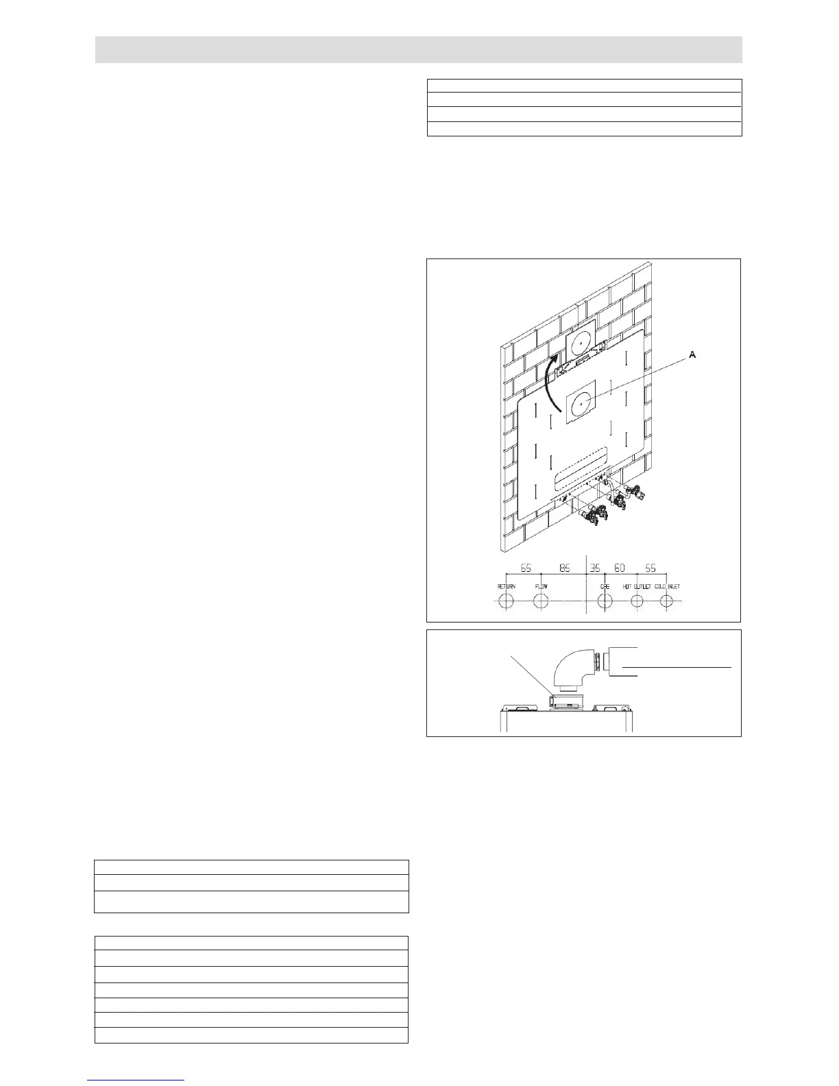
Using the template provided (A), mark and drill a 125mm hole
for the passage of the ue pipe. The hole should be drilled to
ensure any condense uid that forms, is allowed to drain back to
the appliance (see g. 12). The xing holes for the wall-mounting
bracket should now be drilled and plugged, an appropriate type
and quantity of xing should be used to ensure that the bracket
is mounted securely. Once the bracket has been secured to
the wall, mount the appliance onto the bracket.
FITTING THE TELESCOPIC HORIZONTAL FLUE KIT
In some instances It may necessary to cut the inner 60mm pipe
of the ue bend at the point indicated (g.12a pos. A) to allow
for easier insertion to the boiler ue spigot.
FITTING THE HORIZONTAL FLUE KIT
Carefully measure the distance from the centre of the appliance
ue outlet to the edge of the nished outside wall (dimension
X). Add 65mm to dimension X to give you Dimension Y (see
g 12). Measure dimension Y from the terminal end of the con-
centric ue pipe and cut off the excess ensuring any burrs are
removed. Pass the concentric ue pipe through the previously
drilled hole. Fit the ue bend to the boiler ue outlet and insert
the concentric ue pipe into the ue bend ensuring the correct
seal is made. Using the clamp, gasket, and screws supplied,
secure the ue bend to the appliance ue spigot.
NOTE
Fit the internal (white) trim to the ue assembly prior to con-
necting the ue pipe to the bend.
You must ensure that the entire ue system is properly sup-
ported and connected. Seal the ue assembly to the wall using
cement or a suitable alternative that will provide satisfactory
weatherproong. The exterior trim can now be tted.
SECTION 4 - INSTALLATION
Fig. 10
Terminal or
extension
Outer clamps