15
• A 130mm hole is required for the passage of the concentric
terminal through the ceiling and/or roof.
Depending on site conditions it may be preferable to install the
terminal assembly prior to tting the twin ue pipes.
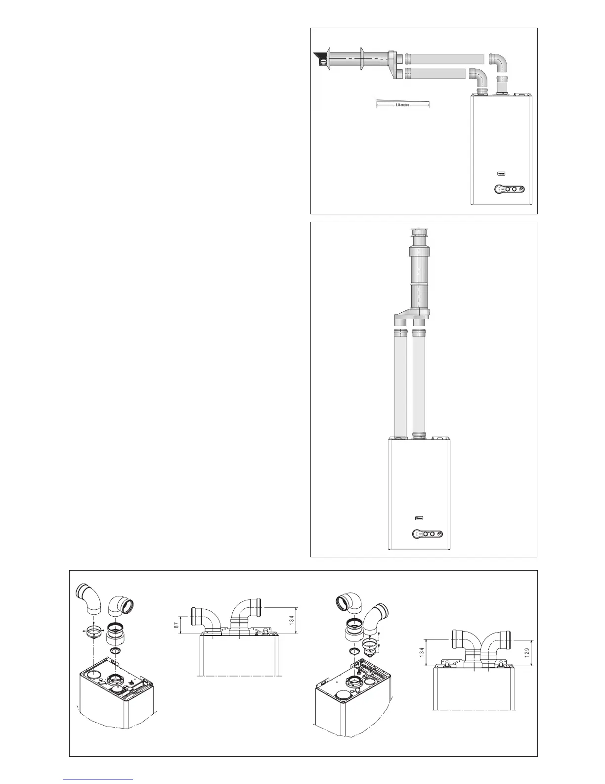
Fit the appropriate ashing plate to the roof and insert the ver-
tical ue terminal through the ashing plate from the outside,
ensuring that the collar on the ue terminal ts over the ashing.
Push-t the twin ue pipes onto the concentric to twin converter
ensuring that the exhaust pipe connects to the exhaust con-
nection on the concentric to twin converter.
If necessary cut the plain ends (male) of the twin ue pipes to
allow connection to the concentric to twin converter.
NOTE
• Before cutting twin ue pipes ensure allowances have been
made for connection onto the previous piece and onto the
concentric to twin converter. The last twin ue pipes must be
pushed 50mm onto the male spigots of the concentric to twin
converter.
• You must ensure that the entire ue system is properly sup-
ported and connected.
• Ensure that any horizontal sections of pipe have a 1º fall
towards the appliance (17mm per 1000mm).
Fig. 13c
Fig. 14
4.6 CONNECTING THE GAS AND WATER
The appliance is supplied with an accessory pack that includes
service valves.
The service valves are for welding. The accessory pack contains
sealing washers’ etc, for use with the service valves.
NOTE
It will be necessary to hold the valve with one spanner whilst
tightening with another
4.6.1 GAS (g. 16)
The appliance is supplied with a 22mm service valve, connect
a 22mm pipe to the inlet of the valve and tighten both nuts.
NOTE
It will be necessary to calculate the diameter of the gas supply
pipe to ensure the appliance has an adequate supply of gas.
4.6.2 FLOW & RETURN (g. 16)
The appliance is supplied with 22mm service valves for the
ow and return connections, connect a 22mm pipe to the inlet
of each valve and tighten both nuts.
NOTE
Depending on system requirements, it may necessary to in-
crease the size of the ow & return pipe work after the service
valve connections.
4.6.3 COLD WATER INLET (g. 16)
The appliance is supplied with a 15mm combined stopcock
and double check-valve, connect a 15mm pipe to the inlet of
the stopcock and tighten both nuts.
4.6.4 HOT WATER OUTLET (g. 16)
The appliance is supplied with a 15mm outlet connection, con-
nect a 15mm pipe to the outlet connection and tighten both nuts.
1-deg = 17mm
Fig. 15