24
g. 37
7.3.2 GAS VALVE MAXIMUM SETTING
Set the CO
2
button at maximum (see 7.3.1), once the maximum
is obtained check that it corresponds with the appropriate CO
2
value (Maximum) for the respective appliance (see 2.11). If
the CO
2
reading is correct, proceed to gas valve minimum
setting (7.3.3).
However, if the CO
2
reading is incorrect, the maximum gas
pressure must be adjusted as follows:
• using a 2.5mm Allen key, very slowly turn the maximum ad-
justment screw (see g. 37) – clockwise to decrease, counter
clockwise to increase – until the correct value is displayed on
the CO
2
analyser (allow time for the analyser to stabilise).
7.3.3 GAS VALVE MINIMUM SETTING
Set the CO
2
button at minimum (see 7.3.1), once the minimum
is obtained check that it corresponds with the appropriate CO
2
value (Minimum) for the respective appliance (see 2.11). If the
CO
2
reading is correct, proceed to completion (7.3.4).
However, if the CO
2
reading is incorrect, the minimum gas
pressure must be adjusted as follows:
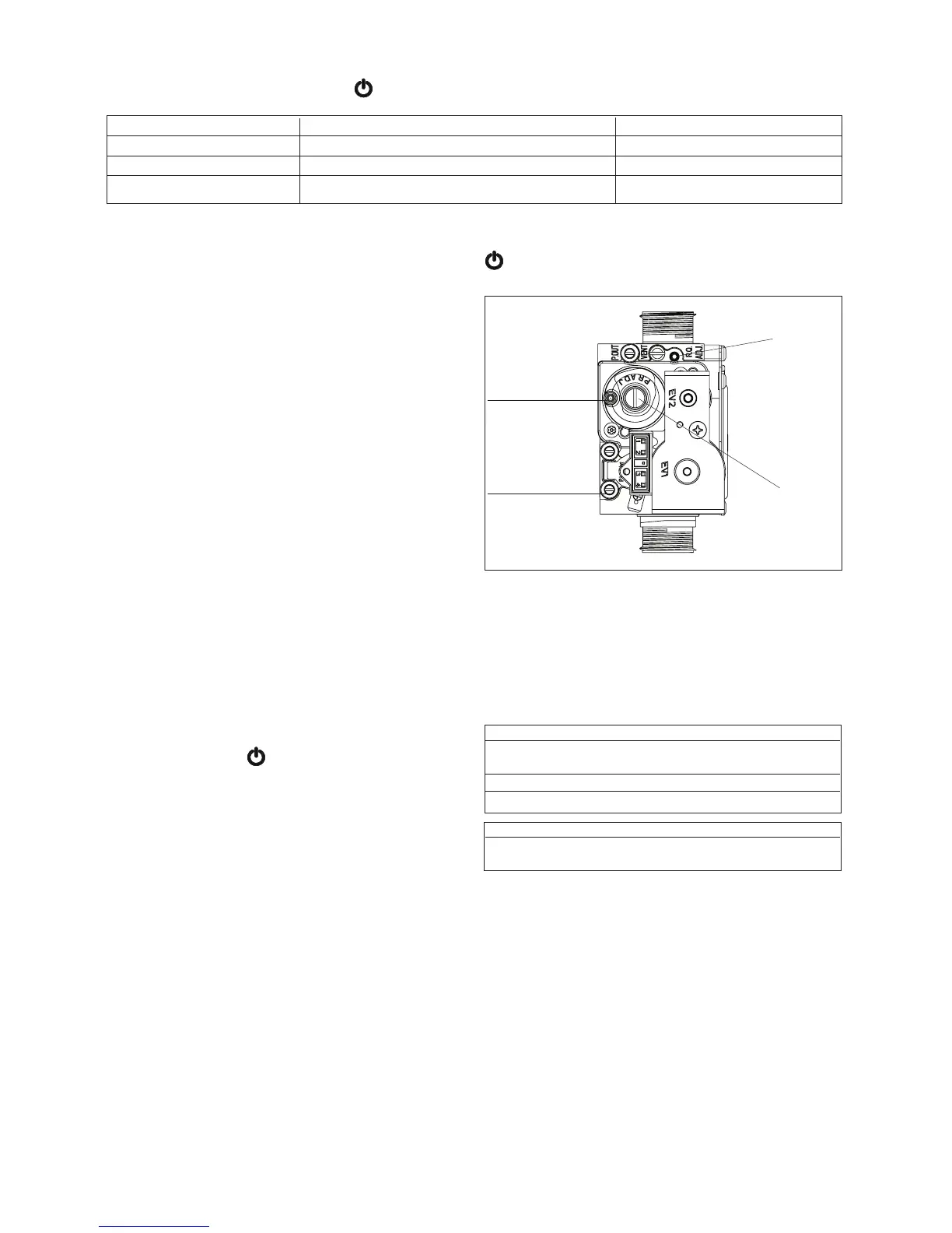
• locate the minimum adjustment screw (g. 37), using a suit-
able screwdriver remove the protection plug
• using a 4mm Allen key, very slowly turn the minimum adjust-
ment screw (see g. 37) - clockwise to increase, counter
clockwise to decrease - until the correct value is displayed
on the CO
2
analyser (allow time for the analyser to stabilise).
7.3.4 COMPLETION
On completion of the combustion analysis check and/or any
gas valve adjustment, ret the plug (g. 36 L2) and move the
mode selector throught
position. Remove the test probe
from the test point and ret the sealing screw/s and/or cap.
IMPORTANT
A GAS TIGHTNESS CHECK MUST BE CARRIED OUT IF ANY
GAS CARRYING COMPONENTS HAVE BEEN REMOVED,
REPLACED OR DISTURBED.
7.4 COMBUSTION ANALYSIS TEST
A combustion analysis check can easily be carried out on the
appliance via the test points located on the top of the applian-
ce (see 7.3).
• Operate the boiler in combustion analysis mode (see 7.3.1)
• Insert the ue gas analyser probe into the ue gas test point
(see g. 33) and compare the values with those shown in
section 2 (Nat. Gas) or section 10 (LPG). If different adjust
the gas valve according to 7.3.1, 7.3.2, & 7.3.3.
The appliance will operate in CO2 mode for approximately
15minutes.
Note: If a measured CO/CO2 ratio of 0.004/1 or less AND a
CO reading of less than 350ppm cannot be achieved, please
contact Vokera technical for advice.
7.5 CHECKING THE EXPANSION VESSEL
Carry out the component removal procedure as described in
6.4. You must ensure that the boiler is completely drained of
water. Using a suitable pressure gauge, remove dust cap on
expansion vessel and check the charge pressure. The cor-
rect charge pressure should be 1.0 bar ± 0.1 bar. If the charge
pressure is less, use a suitable pump to increase the charge.
7.3.1 CO
2
FUNCTION SETTINGS
Locate the CO
button (see 7.3)
Select the main selector switch in position
CO
2
FUNCTIONS ACTION ON THE BUTTON LED STATUS
combustion analysis mode press once = burner running at maximum heating yellow led blinking
gas valve maximun setting press twice = burner running at maximum DHW yellow led blinking + red led xed
gas valve minimum setting press three time = burner running at minimum yellow led blinking + green led xed
NOTE
1 - Any additional pressing of CO
button after the third time the burner switched between maximum DHW and minimum.
2 - To restart the CO
function it is necessary to pass throught the position with the main selector switch
NOTE
You must ensure the drain valve is in the open position whilst
re-charging takes place. Replace the dust cap and carry out
the relevant commissioning procedure (section 5).
7.6 EXTERNAL FAULTS
Before carrying out any faultnding or component replacement,
ensure the fault is not attributable to any aspect of the installation.
7.6.1 INSTALLATION FAULTS
Symptom Possible cause
No led/ignition Check wiring/check electrical
supply
No hot water Check pipe-work
No heating Check external controls
Fault Possible cause
Red led xed Check gas supply, check ue
system, check polarity
7.7 ELECTRICAL CHECKS
Any electrical checks must be carried out by a suitably quali-
ed person.
7.7.1 EARTH CONTINUITY TEST
Isolate the appliance from the electrical supply, and using a
suitable multi-meter carry out a resistance test. Connect test
leads between an appliance earth point and the earth wire of
the appliance supply cable. The resistance should be less than
1 OHM. If the resistance is greater than 1 OHM check all earth
wires and connectors for continuity and integrity.
7.7.2 SHORT CIRCUIT CHECK
Isolate the appliance from the electrical supply, and using a
suitable multi-meter, carry out a short circuit test between the
Live & Neutral connections at the appliance terminal strip.
Repeat above test on the Live & Earth connections at the ap-
pliance terminal strip.
NOTE
Should it be found that the fuse has failed but no fault is in-
dicated, a detailed continuity check will be required to trace
Minimum
screw
Inlet gas pressure
connection
Compensation pipe
connection
Maximum
screw