28
10.1 RELATED DOCUMENTS
BS 5440 PARTS 1 & 2 FLUES & VENTILATION REQUIREMENTS
BS 5449 PART 1 FORCED CIRCULATION OF HOT WATER SYSTEMS
BS 5482 PART 1 DOMESTIC BUTANE & PROPANE GAS BURNERS IN PERMAMENT DWELLINGS
BS 5546 INSTALLATION OF GAS HOT WATER SUPPLIES FOR DOMESTIC PURPOSES
BS 6798 INSTALLATION OF BOILERS OF RATED NOT EXCEEDING 60kW
SECTION 10 - LPG INSTRUCTIONS
10.6 CHECKING THE CO
2
AND ADJUSTING THE
GAS VALVE
THE GAS VALVE MUST BE SET-UP OR ADJUSTED WITH
THE AID OF A PROPERLY CALIBRATED FLUE GAS
ANALYSER.
Isolate the appliance from the electrical supply and remove
the appliance casing as described in 4.7.1. Restore the elec-
trical supply to the boiler and switch the boiler to the OFF
mode.
Have access to the printed circuit board, locate and open the
closing plug on the dash board (L2), locate and press the CO
button (see g. 36 pos. SW1). Press the button the number of
times according the function requirement as par 7.3.1.
Set the ue gas analyser to read CO2, allow the burner to
stabilise and insert the probe into the ue analysis test point
(Y1-Z1 g. 33). The appliance will operate in CO2 mode for
approximately 15 minutes.
10.6.1 CO
2
FUNCTION SETTINGS
Locate the CO
button (see 7.3)
Select the main selector switch in position
CO
2
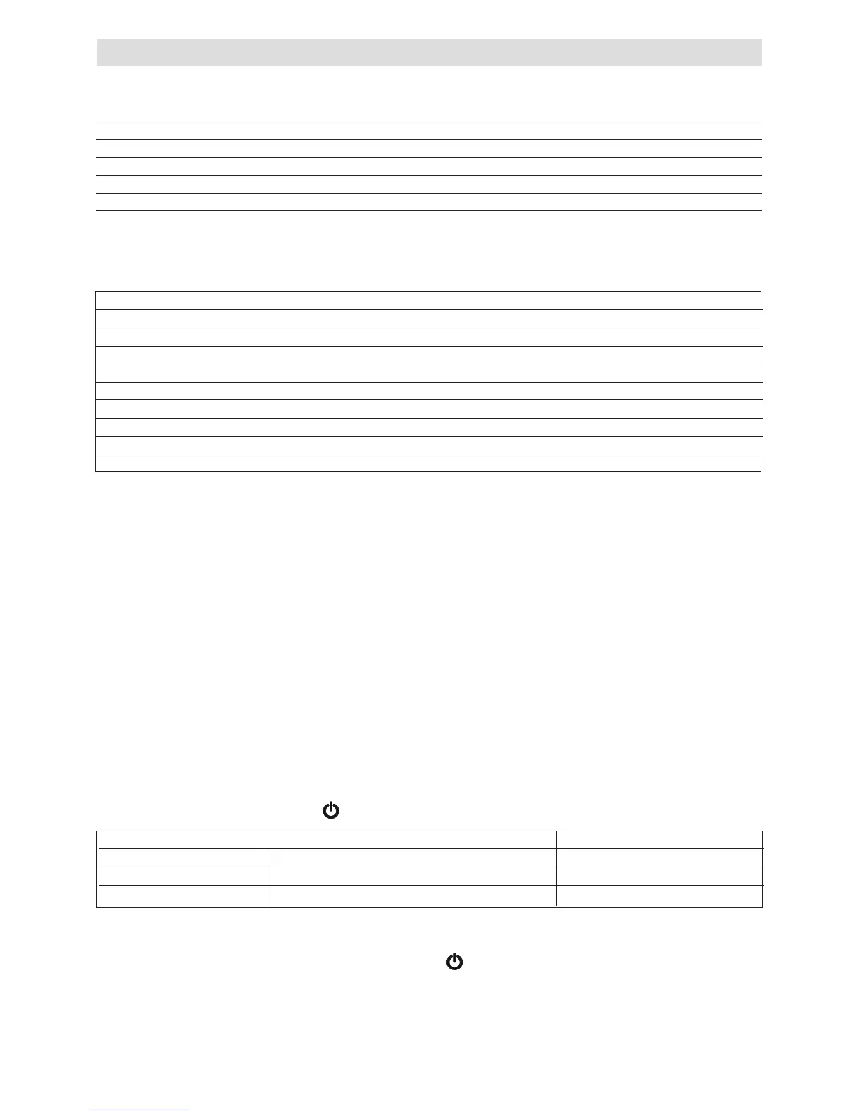
FUNCTIONS ACTION ON THE BUTTON LED STATUS
combustion analysis mode press once = burner running at maximum heating yellow led blinking
gas valve maximun setting press twice = burner running at maximum DHW yellow led blinking + red led xed
gas valve minimum setting press three time = burner running at minimum yellow led blinking + green led xed
NOTE
1 - Any additional pressing of CO
button after the third time the burner switched between maximum DHW and minimum.
2 - To restart the CO
2
function it is necessary to pass throught the position with the main selector switch
10.3 CONVERTING THE APPLIANCE GAS TYPE
To convert the appliance to another gas type it is necessary to
change the injector and adjust the gas valve (CO
2
).
• To change the injector see 6.12.1
• To replace the ange on the silencer (only Excel 29) see 6.15
• To adjust CO2 values see 10.6
10.4 GAS SUPPLY
The gas supply must be connected to the appliance by a com-
petent LPG installer and must be of sufcient size to supply
the appliance at its maximum output. An existing supply must
be checked to ensure that it is of adequate size to deal with
the maximum rated input of this and any other appliances that
it serves.
10.5 GAS SUPPLY INSTALLATION
The entire installation including the meter must be purged and
checked for gas tightness.
10.2 TECHNICAL DATA
Gas Pressures Excel 25 Excel 29
Inlet pressure 37.0 mbar 37.0mbar
Heating maximum gas rate (kg/hr) 1.55 1.94
DHW maximum gas rate (kg/hr) 1.94 2.25
Minimum gas rate (kg/hr) 0.39 0.47
Injector size 3.9 mm 4.3 mm
Silencer ange 27 mm 29 mm
CO
2
@ maximum output (%) 10.5 10.5
CO
2
@ minimum output (%) 10.5 10.5
CO
@ maximum output (ppm) 190 250
CO
@ minimum output (ppm) 20 25