54
Proceed as follows to identify the 3-phase rotating direction:
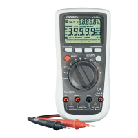
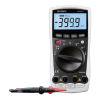
- TurntheDMMonandselectmeasuringfunction“Motor”.
Thedisplayshows“AC”andtheunit“V”.
- Plug the red measuring line into the V measuring jack (E)
and the black measuring line into the COM measuring jack
(D).
- Keepthebutton“SELECT”pressedforapprox.2seconds.
Twobeepsareoutputandthelockicon(H19)willash.
The automatic measuring range setting is deactivated and
the 600 V-range is selected. The display will show approx.
0.0 V.
- Connect the black measuring prod to the outer conductor
L3. This connection remains unchanged throughout the
test. Connect the red measuring prod to the outer conduc-
tor L1.
- Once the meter recognises two outer conductors, the nor-
mal voltage will be displayed and the lock icon will remain lit.
- Now switch the red measuring prod to outer conductor L2
within 5 seconds. If the time for measuring point change
is exceeded, the DMM will interrupt the measurement and
the function must be restarted.
- The meter will evaluate the phase offset of the three sub-
sequently determined outer conductors at correct measur-
ing point change, and display the rotating direction via two
symbols in the display. The arrow direction of the symbols
shows the respective rotating direction:
Clockwise = right turning
Counter-clockwise = left-turning
- Foranothermeasurementpushthebutton“SELECT”once
briey.Todeactivatethefunction,keepthe“SELECT”but-
ton pushed for at least 2 seconds.
- Remove the measuring lines from the object to be meas-
ured after completion of the measurement and switch off
the DMM.
Thefunctionbuttons“RANGE”,“MAXMIN”,“REL”,“Hz”and“HOLD”aredeactivatedinthismeasuring
function and cannot be selected.
When measuring 3 phase motor drives with variable frequency speed control interference can occur (PWM
interference).Inordertominimizethisinterferencealongermeasuringtime(≥30s)isrequired.
In this case, the nominal voltage indicated is only a reference value. The precision indicated is not valid for
speed-controlled motor drives.