Standard STD 101-0001
Volvo Group
Version
4
Page
24
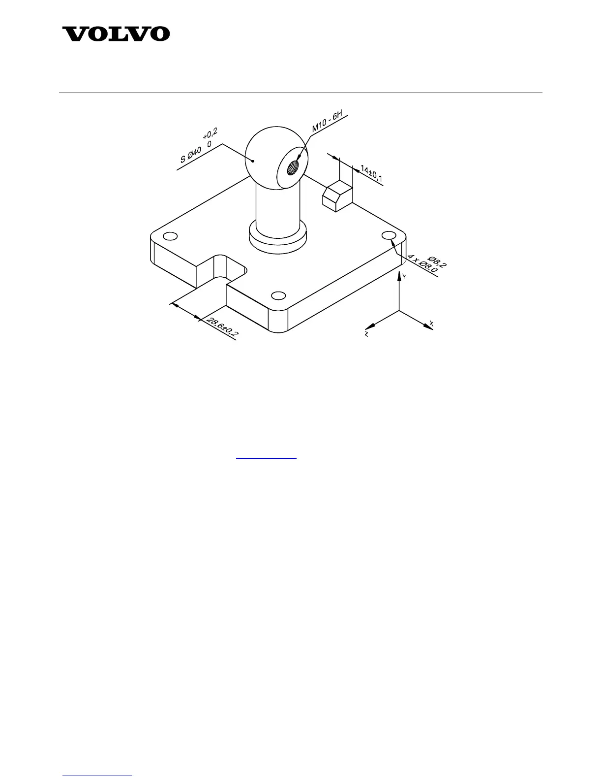
Figure 20 – Placement and attachment for linear dimensions
4.6 Datum applications
This section establishes practices for organizing, attaching and displaying datum indicators, datum target indicators
and related information associative with models. Requirements and recommendations for correlating datum
features to the coordinate axes of the model space are given.
4.6.1 Model requirements
In 3-D annotation, the rules from standard STD 112-0002 – Datums and datum system apply with the following
exception and addition:
• The datum indicator shall not be attached on a single extension line of model feature outlines.
NOTE: This is an unambiguous method in orthographic views to represent a surface, but it cannot be used on a 3-D
model where it becomes indistinct.
4.6.1.1 Datum system and model coordinate
The following requirements apply to the relationship between the datum systems on the model and the model
coordinate systems:
a) Datum system and coordinate system correspondence
Each datum system shall be associated to a corresponding model coordinate system.
b) Datum system and coordinate system associativity
A definite visual relationship between any datum system and the corresponding coordinate system shall be
preserved throughout navigation and query of the presented design data.
c) Multiple datum system and coordinate system relationship
When more than one datum system is imposed upon the model, each datum system-to-coordinate system
relationship shall be clearly presented and maintained.