Standard STD 101-0001
Volvo Group
Version
4
Page
30
4.7 Geometrical tolerances
In this section, rules for the connection of the tolerance frames to the toleranced features in 3-D environment are
given. Some of these rules differ from the rules stated in
STD 112-0003 which mainly are intended for orthographic
engineering drawings.
Some examples of various tolerance indications in accordance with the rules given in this standard are also shown.
4.7.1 Toleranced features
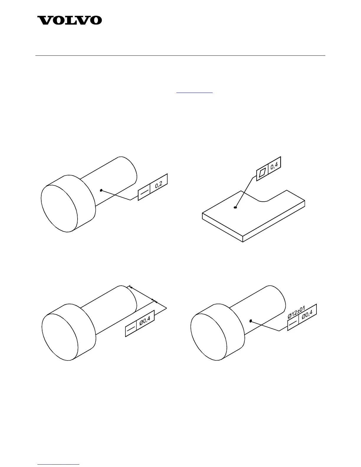
4.7.1.1 The line or the surface itself
When a tolerance applies to a line or to the surface itself, the tolerance frame shall be connected to the toleranced
feature by a leader line that ends with a dot on the surface. See examples in figures 26 and 27.
Figure 26 Figure 27
4.7.1.2 The axis of a cylinder
When the tolerance applies to the axis of a cylinder, this shall be indicated in accordance with one of the ways
shown in figures 28 – 30.
Figure 28 – Current 2-D rule. This can also be used
in 3-D but will often become impractical
Figure 29 – Recommended 3-D method, which is to
connect the leader line with a dot to the
surface and to specify the size dimension
above the tolerance frame