VA41620/VA41630 Evaluation Board User’s Manual
V1.0
4
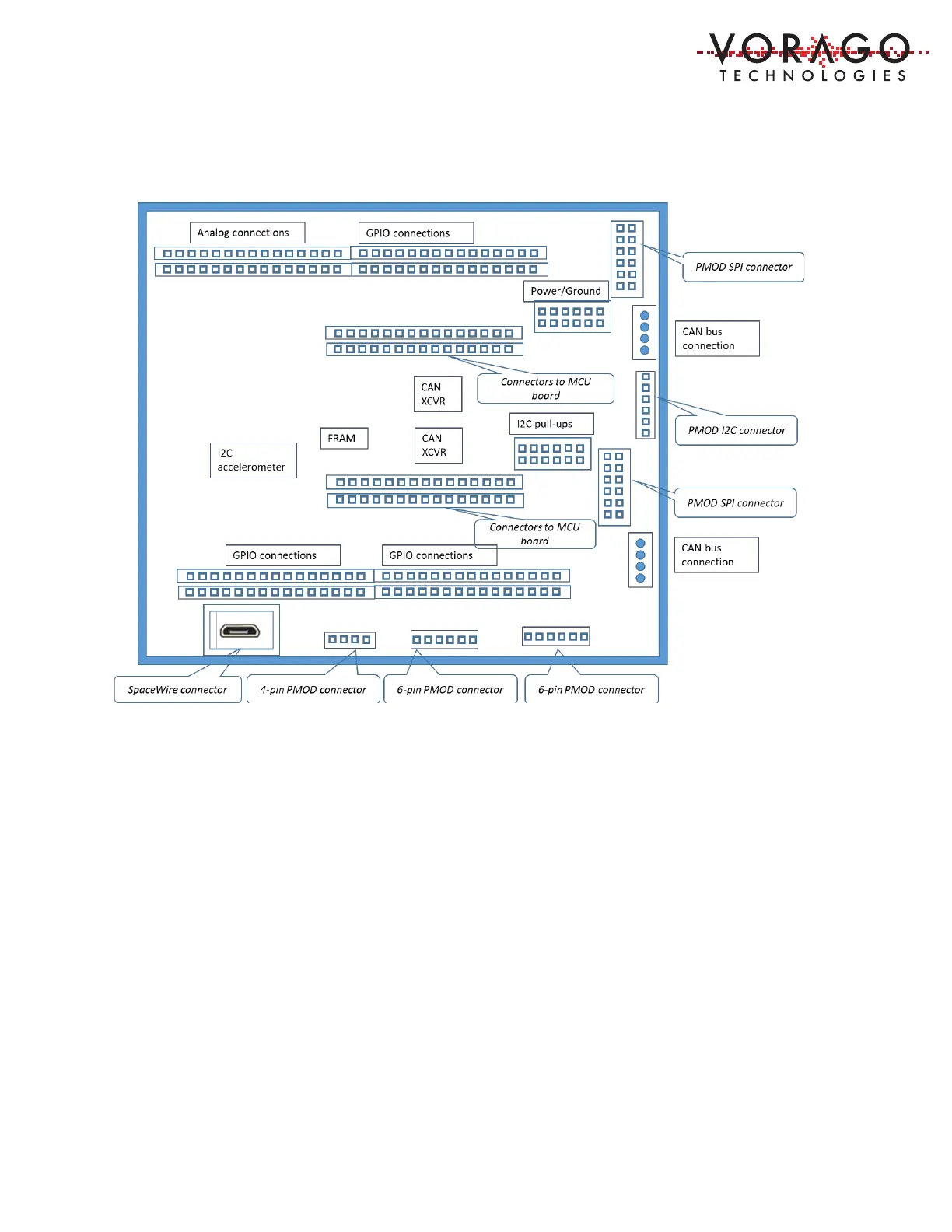
Figure 2 - Block diagram of PEB1 GPIO board
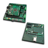
1.3.3 The PEB1 EBI/Ethernet board
The PEB1 EBI/Ethernet board provides additional connectivity to the VA416x0 MCU. To suit
another example of port expansion, covering a different set of peripherals, the External Bus
Interface (EBI)/Ethernet interface board provides access to 41 GPIO pins as well as access to
ADC inputs, DAC outputs, I2C interfaces, CAN interfaces with transceivers, and a connector to
the SpaceWire interface. Two high speed parallel memory devices, an SRAM and a FRAM are
included. The VA416x0 Ethernet peripheral is connected to an external Ethernet physical layer
transceiver device and an RJ-45 connector.
Figure 3 - Block diagram of PEB1 EBI-Ethernet board