WWW.VORONDESIGN.COM
CAD version: ERCF V2
120120
FINAL ASSEMBLY
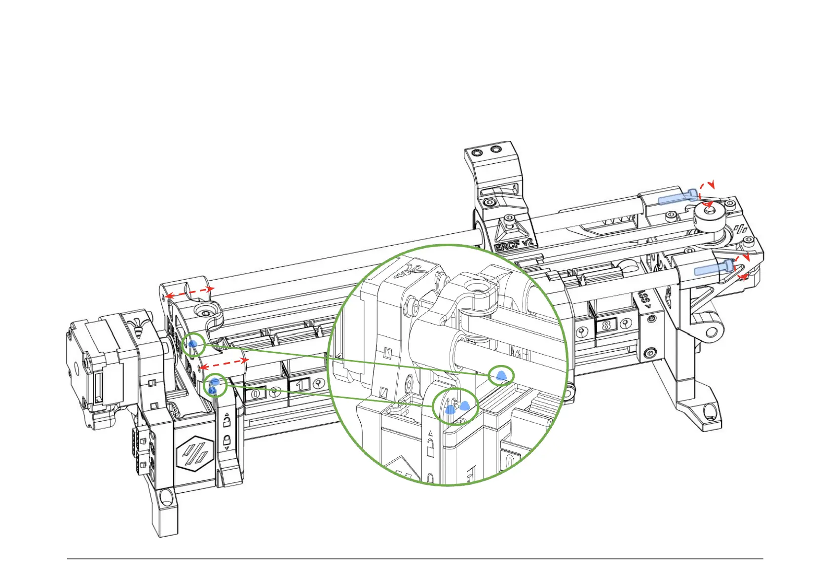
IDLER POSITION
Use the two M3x16 SHCS screws on the
Linear_Axis_Selector_Motor_Support to finely adjust the the
Linear_Axis_Idler_Block position by pushing out the 8mm rods. If you
unscrew these, make sure to push the 8mm rods in so they’re still in
contact with the screws.
The locating bumps on the Linear_Axis_Idler_Block must line up to the
Gear_Box_Top_Panel.
Once the tuning is done, lock the linear axis
using the two Side_Latches.
IDLER ADJUSTMENT