Do you have a question about the VORON STEALTHBURNER and is the answer not in the manual?
Provides recommended settings for 3D printing parts.
Details on how to get assistance via Discord and community channels.
Details on various screws, washers, inserts, and nuts used in the build.
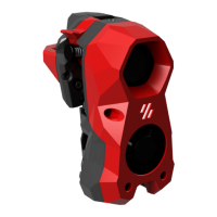
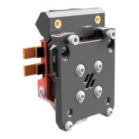
Identification of Voron ClockWork2, StealthBurner, and ADXL mount.
Guidance on installing heat set inserts, including surface placement and PCB options.
Heat set insert locations for cable chains and notes on printer-specific mounts.
How to identify parts printed in accent color using the Voron heart logo.
Guidance on lubricating bearings and correctly orienting the idler assembly.
Notes on spring length, stiffness, and sourcing recommendations.
Ensuring proper fit and installation of bearings into motor plate and main body.
Caution on screw tightening and checking filament path alignment.
Notes on gear quality, set screw seating, and thread locker application.
Steps for inserting filament and verifying drive gear and shaft clearance.
Ensuring free arm movement and adjusting filament tension via the knob.
Adjusting motor position for correct gear meshing and play.
Instruction to tighten the second motor bolt after adjustments.
Opening the latch and cautionary advice on bolt tightening.
How to identify parts and different hotend types like CW1/CW2.
Adding heat set inserts for the ADXL PCB mount for Input Shaper calibration.
Identification of Revo Voron Heatsink, HeaterCore, and Nozzle.
Instructions for routing hotend wires and bending strain relief.
Instructions for mounting the tool cartridge and setting PTFE tube stickout.
Instructions for removing built-in supports using flush cutters.
Wiring for logo and toolhead LEDs, including diagrams and soldering.
Instructions for installing LED diffusers and masks for optimal light spread.
Guidance on routing LED wires to the correct exit point.
Correct fan orientation, angled insertion, and wire routing.
Instructions for preparing the 5015 fan by removing mounting ears.
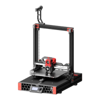
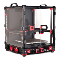
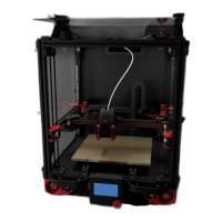
Guidance on selecting the correct carriage version for your printer.
Reference to manual for belts and mounting probes on the carriage.
Setting the initial position of the probe, approximately 6mm below the plastic part.
Information on accessing the mounting bolt via an access hole.
Explanation for using longer bolts as a quality-of-life feature.
Mounting ADXL only for vibration testing and input shaper calibration.
Importance of installing spacers to prevent damage to the ADXL board.
Guidance on software setup and calibration after assembly completion.
Information on Discord, subreddit, and reporting issues on GitHub.
| Brand | VORON |
|---|---|
| Model | STEALTHBURNER |
| Category | 3D Printers |
| Language | English |