Do you have a question about the VORON SWITCHWIRE and is the answer not in the manual?
Guidelines for successful part printing using specific materials and settings.
Community service for obtaining printed parts for your printer.
Information on seeking assistance through Discord and community channels.
Recommends specific hex drivers like 2.5mm and 3mm for assembly.
Details on various screws, nuts, and pulleys used in assembly.
Describes F695 Bearings, Heat Set Inserts, and their applications.
Covers Post Install T-Slot Nuts and Self Tapping Screws for assembly.
Guidance on separating and identifying extrusions for the frame assembly.
Explains the blind joint method using M8x16 BHCS for frame construction.
Recommends building on a flat surface and upside down for accuracy.
Instructions to ensure the frame is square and dimensions are correct.
Steps to modify an unmodified carriage for proper hole pattern alignment.
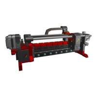
Instructions for assembling the Y-axis idler using bearings and screws.
Guidance on mounting the Y-axis motor, including grub screw advice.
Details on routing the GT2 belt and checking for printed part integration.
Instructions for attaching the front skirt panels using heat set inserts and screws.
Steps for installing the back skirt panels, similar to the front.
How to assemble and orient the Z-axis motor mount with a pulley.
Steps for mounting the X-axis motor, ensuring correct orientation.
Installation of left and right idlers using bearings, shims, and fasteners.
Assembling XZ blocks and ensuring correct orientation of the X-axis.
Shows where to apply heat set inserts for the X carriage components.
Details on assembling the X carriage parts using heat set inserts and nuts.
Instructions for wiring end-stop switches for X and Y axes.
Guidance on installing inductive probes and managing probe wires.
Steps for assembling the tool cartridge, including hotend mounts.
Correct insertion depth for the PTFE tube in the tool cartridge.
Guides wiring path and ensures correct heater block orientation.
Mounting the mains inlet and main power supply unit (PSU).
Installing the PI/Secondary PSU and control board (SKR Mini E3 2.0).
Using WAGO terminals for mains wiring and connecting DC power.
Applying VHB tape for mounting and routing wires using cable raceways.
Instructions for installing deck panels onto the printer frame.
Verifying the PSU's input voltage switch matches local mains voltage.
Wiring the mains inlet according to IEC color scheme, advising professional help.
Connecting 5V Raspberry Pi and 24V Controller Board power.
Illustrates wiring for hotend, fans, motors, and probes.
Detailed diagrams showing connections to the controller board.
Securing the bottom panel using M5x16 BHCS.
Instructions for attaching the spool holder with PTFE tube.
Mounting the heated bed and connecting its wiring.
Attaching a cable cover using M3x8 SHCS.
| Filament Diameter | 1.75mm |
|---|---|
| Heated Bed | Yes |
| Frame Material | Aluminum Extrusion |
| Kinematics | CoreXY |
| Nozzle Temperature | Up to 300°C |
| Layer Resolution | 0.05mm - 0.3mm (depending on nozzle and settings) |
| Nozzle Diameter | 0.4 mm |
| Max Print Speed | 200 mm/s |
| Firmware | Klipper |
| Connectivity | USB |
| Power Supply | 24V |
| Controller | Raspberry Pi + Controller Board (e.g., SKR, BTT) |