Do you have a question about the VORON TAP and is the answer not in the manual?
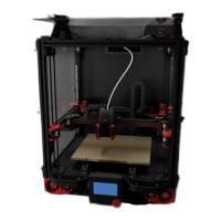
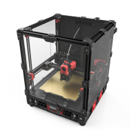
Overview and introductory remarks for the Voron Tap project.
Guidelines for successful part printing, covering process, materials, and specific settings.
Specific print settings including infill, layer height, extrusion width, and wall count.
Convention for naming STL files for primary and accent colors, and part versioning.
Information on where to find assistance via Discord, forums, and Reddit.
How to report documentation issues or suggestions via GitHub.
Recommend downloading CAD files from Github for detailed assembly reference.
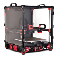
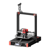
Defines Tap as a nozzle-based z-probe for V2 and Trident printers.
Details the high precision (0.4 µm) achievable with a well-built Tap.
Tap works with any build surface and doesn't require recalibration after changes.
Tap sensor is rated for high temperatures (70-100C) and has proven durability.
Tap uses a single macro and requires no docking or undocking.
Tap eliminates the need for a separate Z endstop.
Tap offers protection against minor and extreme printer crashes.
Warnings about Y-position clearance and mandatory hardware like MGN12H X-Axis and CW2 extruder.
Requirements for a secure bed mount and good printer mechanical condition.
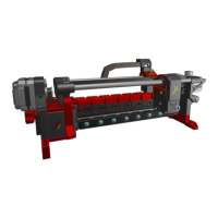
Explains how the toolhead moves on an MGN9 rail using magnets and a photointerrupter switch.
Refers to BOM for sensor part numbers and advises using tested sensors.
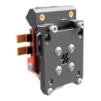
Describes the function of the red center part, housing magnets and triggering the sensor.
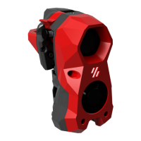
Describes the black front part, connecting to the toolhead and housing the sensor.
Tap is a direct replacement for the X Carriage, mounting the toolhead and extruder.
Illustrates how magnets hold the toolhead, and how it moves to trigger the optical sensor.
Details compatible wired Optek sensors and necessary wiring components like resistors.
Presents the PCB-based sensor option, its advantages, and where to find design files.
Compares sensor types and advises on purchasing prebuilt PCB sensors.
Essential warning against connecting sensors to 24V, which will cause damage.
Step-by-step instructions for wiring the optical sensor with a resistor and MCU.
Identifies the Front, Right Magnet Holder, Center, and Left Magnet Holder parts.
Recommends specific STL files for PCB-based and wired sensor mounts.
Lists general hardware like rails, magnets, nuts, washers, and screws.
Lists the resistor and sensor required for the wired sensor option.
Lists the OptoTap PCB and sensor required for the PCB-based sensor option.
Describes Button Head Cap Screws (BHCS), Socket Head Cap Screws (SHCS), and Flat Head Countersunk Screws (FHCS).
Details magnet specifications, size, and strength preferences.
Explains the usage of M3 nuts (ISO 4032) and washers (DIN 125).
Explains the function and installation of heat-set inserts for strong threaded connections.
Lists and describes necessary tools like soldering iron, angle grinder/dremel, vise, and wiring crimper.
Covers printed cut guides, superglue for threadlocking, and the MGN9 assembly tool.
Instructions for safely removing the carriage, including handling dropped balls.
Step-by-step guide on using the printed tool for carriage installation and ball retention.
Specifies the dimensional tolerance for cutting the MGN9 rail.
Instructions on using the printed guide to mark cut locations on the rail.
Advice on smoothing and cleaning cut rail surfaces to protect bearings.
Guidelines on when supports are used and how to remove them.
Explains the reliance on heat-set inserts and recommends watching a guide.
Guidance on inserting heat-set nuts, emphasizing depth and flush seating.
Step-by-step instructions for pressing magnets into their holders using glue.
Explains the advantage of hex holes for magnet retention.
Instruction to leave 2.5mm clearance for proper toolhead mating with screws.
Advice on gently threading screws into plastic, noting variations for sensor types.
Tips on using zip-ties and printed channels for tidy wire management.
Instructions on angling FHCS screws and tightening them until flush.
Explains the function of specific screws for supporting the toolhead's bottom.
Identifies magnet holders by dots and their correct orientation.
Instructions to snug magnet adjustment screws back for initial setup.
Instructions for installing M3x6, M3x8 screws and M3x12 with heatset as standoff.
Instructions for mounting and wiring an X-carriage mounted switch.
Instructions for pressing the hall effect magnet into its recess.
Instructs to thread belt ends through the center section and secure it.
Guide on tucking excess belt material to keep it out of the way.
Instructions for gently sliding the carriage onto the rail, ensuring smoothness.
Emphasizes the importance of washers for securing the carriage tightly.
Instructions on tucking excess belt material to keep it out of the way.
Instructions for fitting the extruder motor plate tightly on top of Tap.
Explains how to check clearance and trim toolheads if needed to avoid screw interference.
Describes the state of correct toolhead installation, flat and secure against Tap.
Instructions to loosen alignment screws, shake, and retighten magnets for proper alignment.
Guides users to documentation for setup, calibration, and advanced topics.
Recommends Tap-Klipper Instructions on Github for software setup.
Directs users to Discord, forums, and Reddit for assistance and community help.
Instructions for reporting documentation issues or suggestions on GitHub.
| Category | 3D Printers |
|---|---|
| Compatibility | VORON 3D Printers |
| Z-Height Accuracy | High precision |
| Triggering Method | Mechanical |
| Type | Probe |
| Function | Bed leveling |
| Mounting | Toolhead |