Do you have a question about the VORON 1.8 and is the answer not in the manual?
Guidelines for successful part printing, including material and standards recommendations.
Assistance via Discord and GitHub resources for build questions and support.
Metric fastener with a domed head and hex drive, commonly M5.
Metric fastener with a cylindrical head and hex drive, common on Voron.
Nut used with bolts for secure joints, available in M3 and M5.
Nut inserted into aluminum profile slots, used in M3 and M5.
Nut for panel mounting, inserted into aluminum profiles.
GT2 idler used in the Voron motion system.
GT2 pulley used in the Voron motion system.
Used in M5 call-out locations, not to be confused with washers.
Ball bearing with a flange, used in various gantry locations.
Insert melted into plastic for excellent torque and pull-out resistance.
Fastener with pronounced thread, screwed directly into plastic.
Long linear ball bearing used in the Z axis.
Used in print bed for manual tramming and as a spacer.
Guides for identifying and preparing extrusions for frame construction.
Instructions for forming the first corner of the frame, emphasizing flat surface build.
Attaching remaining uprights and positioning Y-extrusions correctly.
Attaching bottom extrusions and rubber feet to complete the base frame.
Details on A/B drive motors, pulley orientation, and grub screw use.
Step-by-step assembly of A and B drives using bearings, shims, and screws.
Verification of A/B drive assembly, focusing on pulley orientation and alignment.
Installing heat set inserts into tension arms; seek Discord for guidance.
Using temporary screws for component alignment during idler assembly.
Verifying the correct assembly of front idler components.
Mounting A and B motors onto the gantry frame.
Sliding the rear crossbar into place and preloading T-nuts.
Assembling the bed frame using extrusions and M5x16 BHCS.
Lubricating and flush installing LM8LUU bearings into the bed frame.
Completing the bed frame assembly with M5x10 BHCS.
Checking the assembled bed frame against provided diagrams.
Lubricating Z axis rods and installing stops to prevent slippage.
Inserting and mounting the Z stage and its motors.
Aligning Z axis rods for smooth, binding-free movement.
Setting up Z axis stepper motors, lead screws, and applying lubrication.
Assembling right and left XY joints, including heat inserts and idlers.
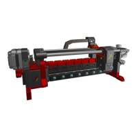
Installing linear rails onto the X beam, with notes on alignment and screw tightness.
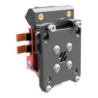
Assembling the X carriage, including microswitch, wiring, and mounting.
Aligning the X axis rails and carriage to ensure smooth operation.
Installing belt clamps using heat set inserts and M3x12 SHCS.
Overview of the CoreXY belt path and motor positioning.
Tips on belt routing, including notes on hidden extrusions for clarity.
Verifying that belts are correctly seated on bearing stacks.
Aligning the X axis to ensure proper belt tension and movement.
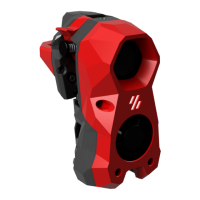
Details on mounting options for different hotends.
Proper installation of the PTFE tube for optimal performance.
Connecting the stepper motor and BMG drive pinion for the extruder.
Assembling the extruder idler and lubricating bearings for longevity.
Checking bearing fit and mounting the motor onto the clockwork body.
Inserting the PTFE tube into the assembled clockwork extruder.
Instructions for disassembling and reassembling the fan unit.
Using a piece of filament as part of the fan assembly process.
Wiring endstops (Y and Z) and ensuring correct component assembly.
Installing the cable chain, considering fixed and free ends.
Applying the print surface and heater pad to the print bed.
Mounting the print bed using springs and screws.
Properly positioning the Z endstop to avoid contact with the print bed.
Installing the power inlet and RJ45 keystone adapter.
Preparing skirt panels and display mounts with heat set inserts.
Mounting the Mini12864 display unit.
Attaching the skirt panels to the printer frame.
Mounting the deck panel and DIN rail for electronics.
Assembling the structural components for the electronics compartment.
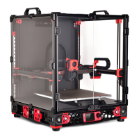
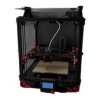
Building the main compartment structure and mounting it to the printer.
Ensuring correct orientation of cutouts for efficient wire routing.
Installing the DIN rail for mounting electronic components.
Mounting the SSR Din mount and preparing the motherboard.
Mounting the power supply units onto the printer frame.
Operating spring-loaded latches to secure electronic panels.
Applying VHB tape to fan mounts for attachment.
Assembling the exhaust housing and its components.
Inspecting the exhaust adapter and mounting the fan.
Preparing rear panels with hammerhead nuts and foam tape.
Mounting the rear panel assembly after tape backing removal.
Attaching panel mounts and applying foam tape for vibration damping.
Applying foam tape to top and side panels for noise reduction.
Installing magnets and attaching front panels with VHB tape and mounts.
Securing the electronics panel and attaching the bottom panel.
Assembling and mounting the filament spool holder.
Attaching the Bowden tube holder and XY caps.
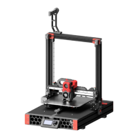
Indicates mechanical assembly is done; wiring/electronics are separate.
Information on obtaining help through Discord and GitHub.
| Brand | VORON |
|---|---|
| Model | 1.8 |
| Category | 3D Printers |
| Language | English |