Section 4
System Configurations
Page 16
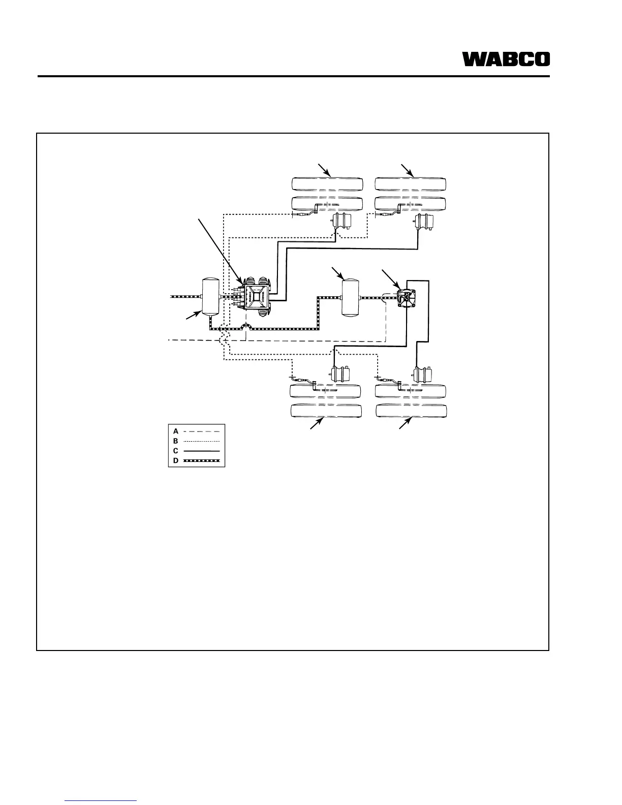
4S/2M Trailer ABS Configuration Diagram for Lift Axle Applications
(Rear Lift Axle Installation Diagram)
For direct tank-mounted installations, see “How to
Install the ECU/Valve Assembly” in Section 6,
"Component Replacement".
Typical Application:
앫 Tandem and Tri-Axle Semi-Trailer
Figure 4.6
A Service/Control Lines
B Sensor Cables
C Service to Brake Lines (Delivery Lines)
D Air Supply/Emergency Lines
1 ECU/Valve Assembly (YE)
2 External Valve (BU)
3 Air Tanks
4 Fixed Axle
5 Lift Axle
1002090e
EXTERNAL
VALVE (BU)
AIR TANK
ECU/VALVE
ASSEMBLY (YE)
AIR TANK
FIXED AXLE
LIFT AXLE
FIXED AXLE
LIFT AXLE
BU1
BU2
YE1
YE2
A Service/Control Lines
B Sensor Cables
C Service to Brake Lines (Delivery Lines)
D Air Supply/Emergency Lines