Section 6
Component Replacement
Page 28
4. Install the wheel hub carefully, so that the
tooth wheel pushes against the sensor as you
adjust the wheel bearings. After installation
there should be no gap between the sensor
and the tooth wheel. During normal operation
a gap of 0.04-inch is allowable.
5. Sensor Output Voltage Test: Use a
Volt/Ohm meter to check the AC output voltage
of the sensors while rotating the wheel at
approximately one-half revolution per second.
Minimum output must be greater than
0.2 volts AC. If minimum output is less than
0.2 volts AC, push the sensor toward the tooth
wheel. Recheck the sensor output.
ABS Relay Valve
Release all pressure from the air system before
you disconnect any components. Pressurized air
can cause serious personal injury.
How to Remove a Standard ABS
Relay Valve
1. Release all pressure from the air system.
2. Disconnect the cable from the valve.
3. Attach labels to identify all of the air lines.
4. Disconnect the air lines from the valve.
5. Remove the mounting fasteners if the valve is
not nipple-mounted directly to the air tank.
6. Remove the valve.
How to Install a Standard ABS
Relay Valve
You must use Schedule 80 pipe nipple (3/4-inch
NPT) to nipple-mount the ABS relay valve securely
to the reinforced air tank to avoid possible serious
personal injury and damage to components.
1. Install the valve with two lock nuts and
washers as required. Tighten the hex nuts to
a torque of 18 lb-ft (24 N폷m) or nipple-mount
the valve directly to the air tank with
Schedule 80 pipe nipple (3/4-inch NPT).
2. Connect the air lines to the ports according
to the labels installed when the air lines
were disconnected.
3. Connect the cable to the valve.
4. Pressurize the brake system. Apply the brakes
and verify there are no air leaks.
The ECU/Valve Assembly
Release all pressure from the air system before
you disconnect any components. Pressurized air
can cause serious personal injury.
The ECU and valve assembly are sealed together
as one unit. To ensure product integrity and avoid
possible damage to the components, do not
attempt to separate the ECU from the valve.
How to Remove the
ECU/Valve Assembly
1. Release all pressure from the air system.
2. Attach labels to identify all air lines.
3. Disconnect the air lines from the
ECU/Valve Assembly.
4. Disconnect the power cable, diagnostic cable,
additional relay valve cable (if used), and all
sensor cables from the ECU/Valve Assembly.
Refer to Figure 6.4 .
5. Remove the ECU/Valve Assembly from its
mounting location:
a. Bracket-mounted: Loosen and remove the
two mounting bolts and lock nuts that hold
the assembly to the mounting bracket.
Remove the assembly.
b. Nipple-mounted to Air Tank: Unscrew the
assembly from the air tank.
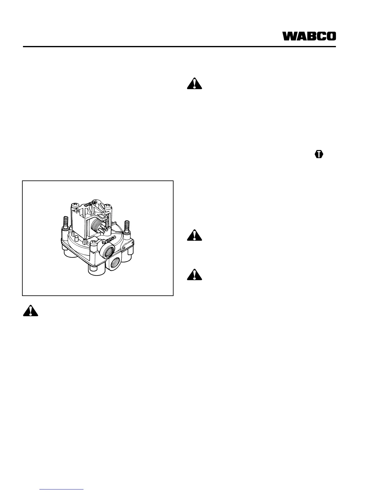
Figure 6.3