Page 29
Section 6
Component Replacement
6. If the assembly being replaced is under
warranty, please return it to the trailer OEM
for replacement.
How to Install the
ECU/Valve Assembly
The ECU/Valve Assembly is supplied with black
protective caps on each sensor connector.
When a sensor cable is not plugged into a sensor
connector, the black cap must remain on the
connector to protect it from dirt and
contamination. See Figure 6.4 .
You must use a Schedule 80 pipe nipple (3/4-inch
NPT) to nipple mount the ECU/Valve Assembly
securely to the air tank to avoid possible serious
personal injury and damage to components.
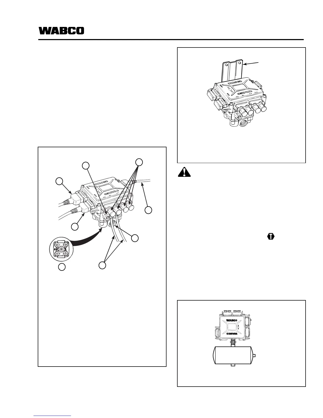
1. Attach the ECU/Valve Assembly to the vehicle:
a. Bracket-mounted: Use two 3/8-inch Grade
8 bolts with prevailing torque nuts to attach
the assembly to the mounting bracket.
Tighten to 18 lb-ft (24 N폷m).
Plug unused supply port (Port 1). Refer to
Figure 6.5 .
b. Nipple-mounted to air tank: Attach the
ECU/Valve Assembly to the air tank, using a
Schedule 80 pipe nipple (3/4-inch NPT).
Tighten securely with exhaust port facing
down. Do not overtighten.
Plug unused supply port (Port 1). Refer to
Figure 6.6 .
Figure 6.4
1 Control Port (Port 4)
2 Black Protective Caps on Unused
Cable Connectors
3 External Relay Valve Cable
4 Supply Port (Port 1)
5 Sensor Cables
6 Port 2 (Any Port May Be Used)
7 Diagnostic Cable (if applicable)
8 Power Cable
* Plug unused port. Use front supply port
for bracket-mounted. Use rear port for nipple
mount.
Figure 6.5
1 Bracket
Plug unused port.
Figure 6.6
Plug unused port.
1002104b
BRACKET
Plug unused port
.
MODULATOR
POWER
DIAGN.
YE2
YE1
BU1
BU2
1002105c