Section 6
Component Replacement
Page 30
2. Connect the air lines to the ports. Follow the
label markers installed when the air lines were
disconnected.
3. Connect the sensor cables, external relay valve
cable (if used), diagnostic cable, and power
cable to the ECU/Valve Assembly. Use the black
protective connector caps included with the
replacement assembly to cover unused cable
connectors.
4. Test the installation using blink
code diagnostics
5. Perform the “Final Test Before Returning A
Trailer to Service” test in Section 7.
How to Install the Blink Code
Diagnostic Tool into the SAE J1587
Diagnostic Connector
The blink code switch and LED lamp are sealed
against dust and contaminants. The red dust cap
protects the switch and lamp during use but is not
an integral part of the diagnostic tool.
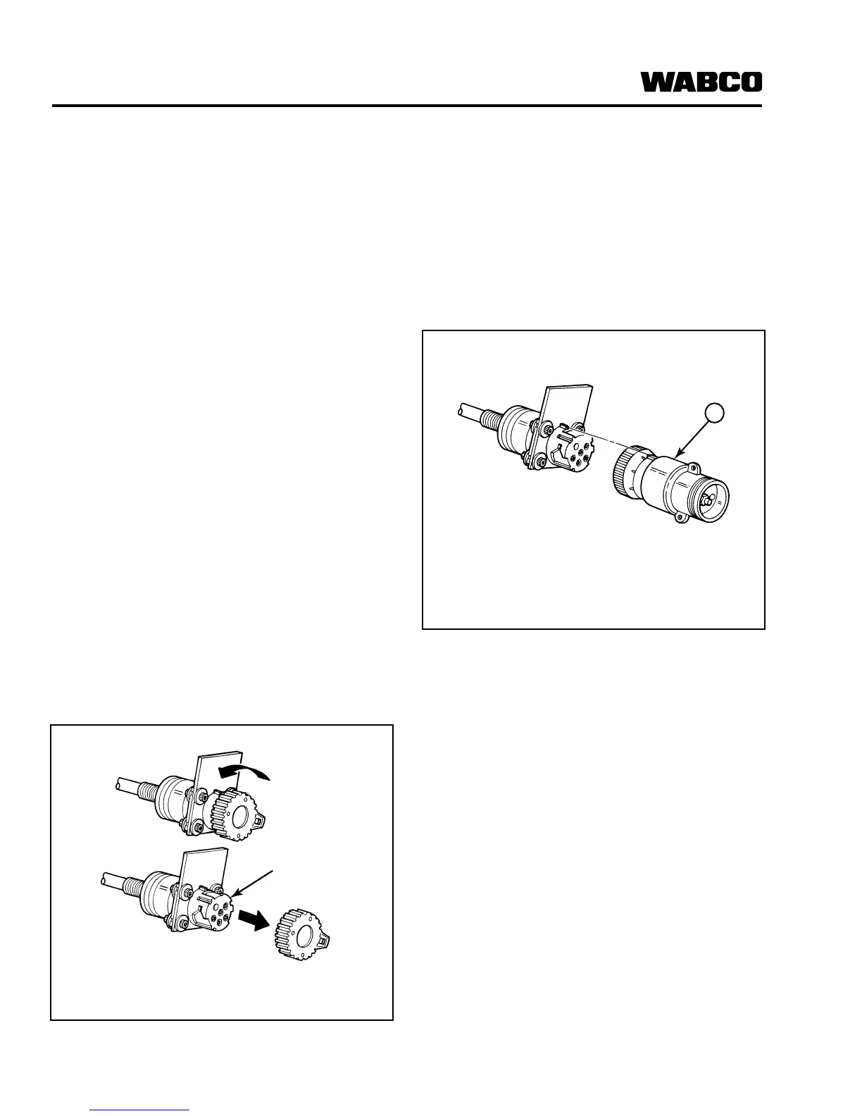
1. Remove the grey protective cap from the
SAE J1587 diagnostic connector. Figure 6.7 .
a. Turn the cap counterclockwise.
b. Pull off the cap.
2. Install the diagnostic tool into the
diagnostic connector.
a. Align the notch on the diagnostic tool with
the notch on the diagnostic connector.
Refer to Figure 6.8 .
b. Push the diagnostic tool firmly into the
connector. Refer to Figure 6.8 .
You must replace the grey protective cap if you
remove the diagnostic tool from the diagnostic
connector. Dirt and contaminants can damage
the connector.
c. Rotate the grey ring on the diagnostic tool
to securely lock the diagnostic tool into
the plug.
3. If the diagnostic tool will remain permanently
installed into the connector:
a. Remove the protective cap and guide wire
that are attached to the mounting bracket.
b. Attach the diagnostic tool and guide wire to
the mounting bracket.
Figure 6.7
1 SAE J1587 Connector
1002106b
SAE J1587
CONNECTOR
Figure 6.8
1 Diagnostic Connector