Page 31
Section 7
Sensor Adjustment & Component Testing
Section 7Sensor Ad justment & Component Test ing
How to Test Wheel
Speed Sensors
At initial installation, no gap must exist between
the sensor and the tooth wheel.
After you install a hub, always check that the
sensor is adjusted properly.
Operating the trailer can cause a gap to develop
between the sensor and the tooth wheel. If the
gap exceeds 0.040-inch, the system may not
function correctly.
To adjust the sensor, twist and push the sensor
through the sensor bracket as far as possible or
until the sensor touches the tooth wheel.
Sensor Test Procedure
1. Disconnect power to the ECU/Valve Assembly.
2. Disconnect the sensor electrical connector
from the ECU/Valve Assembly.
3. Connect the Volt/Ohm meter leads to the two
wire component terminals inside the
disconnected connector.
4. When checking the resistance, the meter must
read 500–2000 ohms.
5. Check and replace the sensor and cables
as required.
6. Repeat Steps 1-5 for each sensor in the system.
Sensor Output Voltage Test
1. Disconnect power from the
ECU/Valve Assembly.
2. Connect the AC Volt/Ohm meter leads to the
sensor terminals inside the connector.
3. Rotate the corresponding wheel at a constant
speed of one-half revolution per second.
4. The output voltage must be greater than
0.2 volts AC.
5. When there is no reading:
a. Trace the cable to verify that the cable
connects to the wheel you turned.
b. Check that you turned the correct wheel.
c. Check that the system is wired correctly.
d. Check that the sensor touches the
tooth wheel.
6. If the Volt/Ohm meter still indicates no reading
or a low reading after following the above
procedures, check and replace the component
and cables as required.
7. Repeat Steps 1-5 for each sensor in the system.
Check ABS Functions
앫 WABCO recommends that you test a vehicle's
ABS after a new installation and after you
diagnose, repair and erase faults in the ABS.
앫 Perform installation tests and blink code
diagnostics using the blink code diagnostic tool
or the MPSI Pro-Link
®
9000 (WABCO Cartridge
Model J 38500-404, version 4.0
or higher).
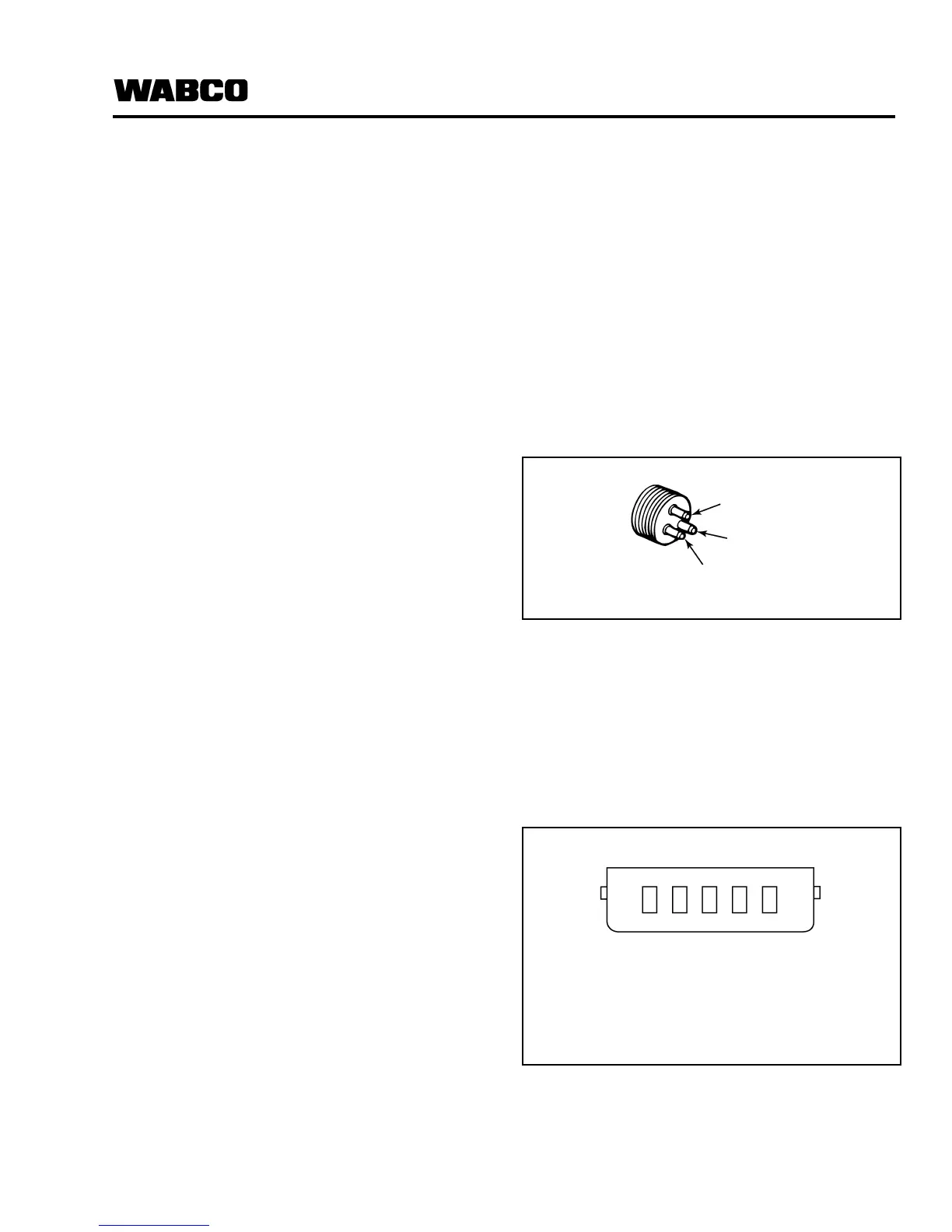
ABS External Modulator Valve
Measure resistance across each valve solenoid coil
terminal and ground on the ABS valve to ensure
4.0 to 8.0 ohms. Valve and cable pinouts are
illustrated in Figure 7.1 .
앫 To check the cable and the ABS valve as one
unit, measure resistance across the pins on the
ECU connector of the harness. See Figure 7.2 .
– For 2S/1M, 2S/2M, and 2S/4M systems,
measure the resistance across pins 1 and 3
and pins 2 and 3.
– For 4S/3M systems (“Y” cable connectors),
measure across pins 3 and 4 and pins 3 and 5.
– Resistance should be between 4.0 and
8.0 ohms for each measurement. Figure 7.2 .
앫 If the resistance is greater than 8.0 ohms clean
the electrical contacts in the solenoid. Check the
resistance again.
Figure 7.1
Figure 7.2
1 Exhaust Solenoid
2 Inlet Solenoid
3 Ground Terminal
4 Exhaust Solenoid (4S/3M only)
5 Inlet Solenoid (4S/3M only)
1003297a
GROUND
TERMINAL
EXHAUST
SOLENOID
INLET
SOLENOID