Page 17
Section 4
System Configurations
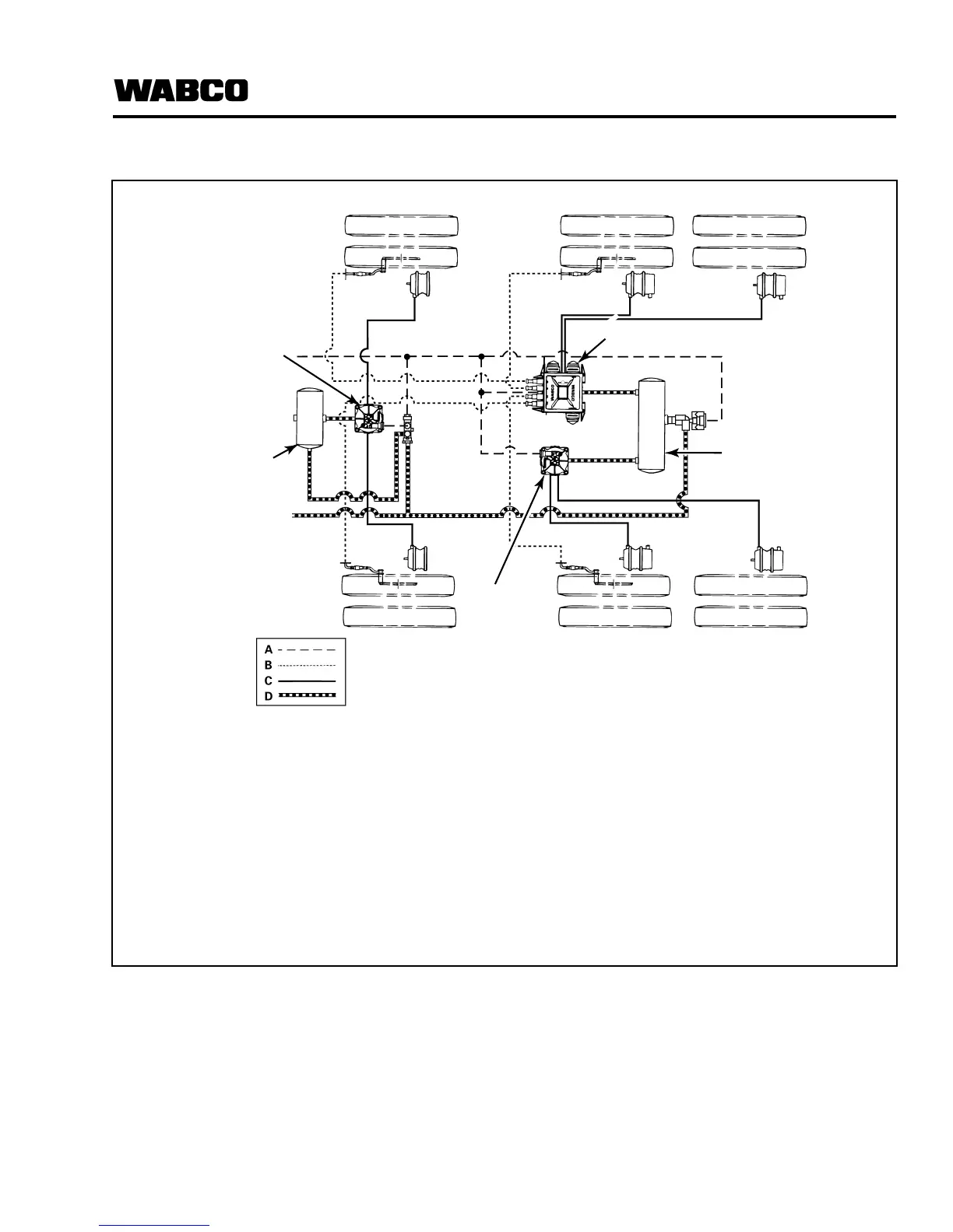
4S/3M Trailer ABS Configuration Installation Diagram
Typical Application:
앫 Tandem with Lift Axle
앫 Tri-Axle Semi-Trailer
앫 Semi-Trailer with Lift Axle
앫 Full Trailer (Drawbar Trailers)
Sensors may be installed on either axle,
depending upon suspension and other
vehicle characteristics.
Figure 4.7
A Service/Control Lines
B Sensor Cables
C Service to Brake Lines (Delivery Lines)
D Air Supply/Emergency Lines
1 ECU/Valve Assembly (YE)
2 External Valve (RED)
3 External Valve (BU)
4 Air Tanks
1003293e
BU1
BU2
YE2
YE1
AIR TANK
ECU/VALVE
ASSEMBLY (YE)
AIR TANK
EXTERNAL
VALVE (BU)
EXTERNAL
VALVE (RED)
A Service/Control Lines
B Sensor Cables
C Service to Brake Lines (Delivery Lines)
D Air Supply/Emergency Lines