Page 35
Section 7
Sensor Adjustment & Component Testing
Sensor Installation Test (ECU Part
Numbers 472 500 012 and 472 500 013 0)
Purpose of Test: To verify proper sensor gap,
sensor hook-up to the ECU, ABS valve operation,
and pneumatic plumbing connections of the
WABCO Easy-Stop™ ABS on a new trailer.
1. Remove power from the ABS.
2. Raise sensed wheels so that they may
be rotated.
3. Go to the diagnostic tool. Reapply power to
the ABS.
앫 If there is no diagnostic tool on the trailer,
temporarily install one for this test. You
must use a diagnostic tool to complete the
Sensor Installation Test.
4. Check the diagnostic tool to verify the status of
the yellow LED. Figure 7.3 .
앫 If LED comes ON and stays ON, go to Step 5.
앫 If LED does not light, verify adequate power
is applied to the system. Make the
necessary repairs.
5. Press and release the blink code switch three
times for Sensor Installation Test Mode, one
second each time, separated by a release time
of one second.
앫 The LED should display eight rapid flashes.
This indicates the Sensor Installation Test
Mode. Then, the LED will continuously
display the system configuration code:
– 2 Flashes = 4S/3M
– 3 Flashes = 4S/2M
– 4 Flashes = 2S/2M
– 5 Flashes = 2S/1M
앫 If this does not occur, repeat Step 4.
앫 Attach the emergency and control air lines to
the trailer. Fill air tanks to release the spring
brakes.
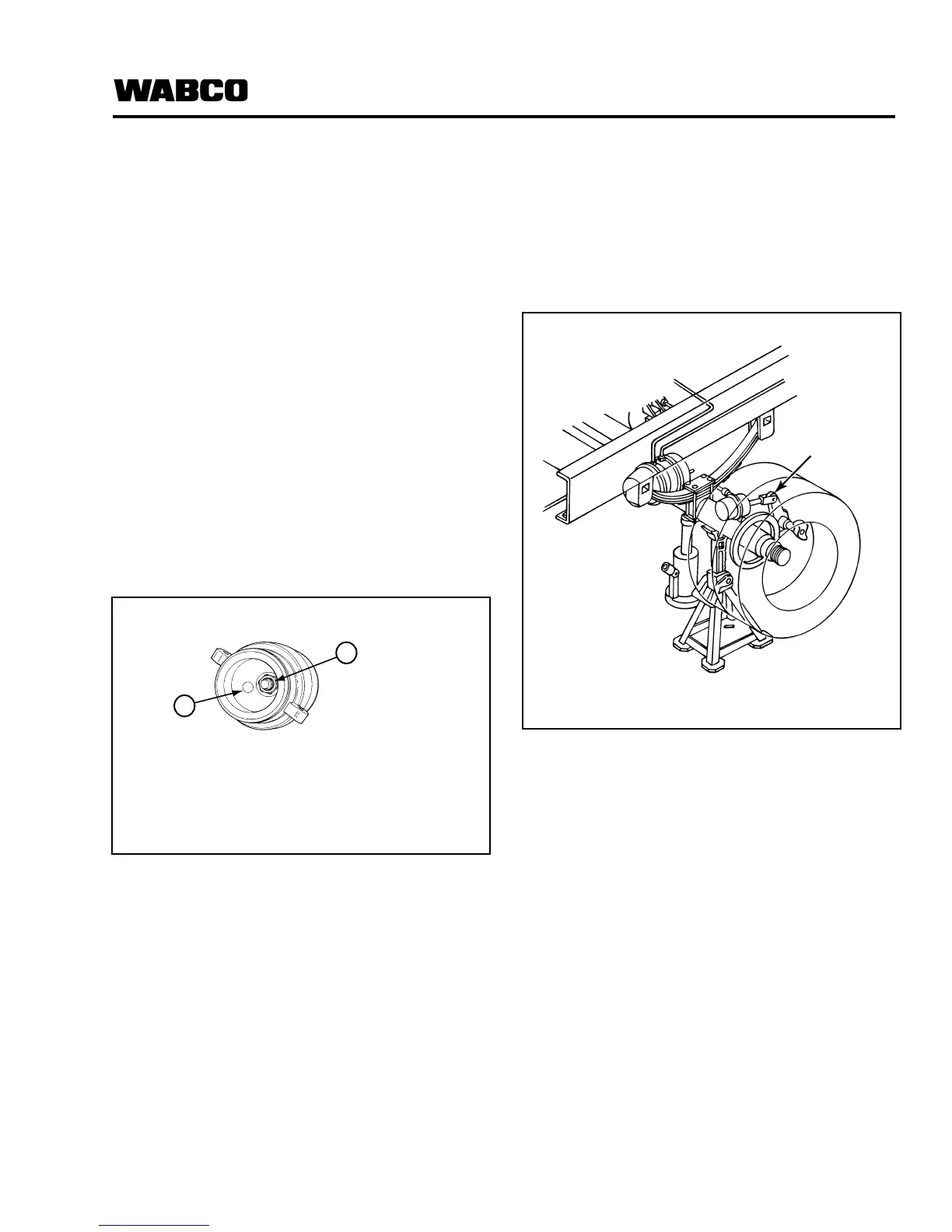
6. Rotate each sensed wheel — ONE AT A TIME —
at a rate of 1/2 revolution per second. Apply
control pressure to activate the brakes. Refer to
Figure 7.4 .
7. Observe the automatic slack adjuster on the
rotated wheel. It must move in and out as
the ABS valve cycles. This indicates a
proper installation.
앫 If the slack adjuster on the rotated wheel
does not move — but the slack adjuster on
the opposite wheel does move — the sensor
leads are reversed or the air line is plumbed
wrong. Correct the installation.
앫 If the slack adjuster on the rotated wheel
does not move, there may be a sensor gap
problem. Check the sensor gap and make
the necessary repairs.
8. Repeat Steps 6 and 7 on the remaining
sensed wheels.
9. If you installed a diagnostic blink code tool for
this test, remove it. Replace the protective cap
over the connector.
Figure 7.3
1 Blink Code Switch
2 LED Lamp
Figure 7.4
1 Slack Adjuster