Marine Head Manual P/N 24533 2 June 25, 2002
THANK YOU FOR PURCHASING A
MICROPHOR
®
PRODUCT!
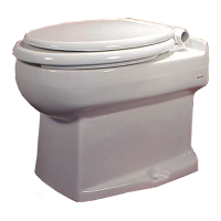
Your Microflush
®
Marine Head is designed to
provide you with years of reliable service while
using only two quarts of salt or fresh water per
flush. Please read this Owner's Manual completely
prior to installation of your Microflush Marine
Head. This will familiarize you with all of the
proper installation and operation requirements.
CUSTOMER SERVICE - Please contact your
local Microphor dealer for parts and service. For a
list of dealers, please contact Microphor at the
addresses listed on the cover of this manual.
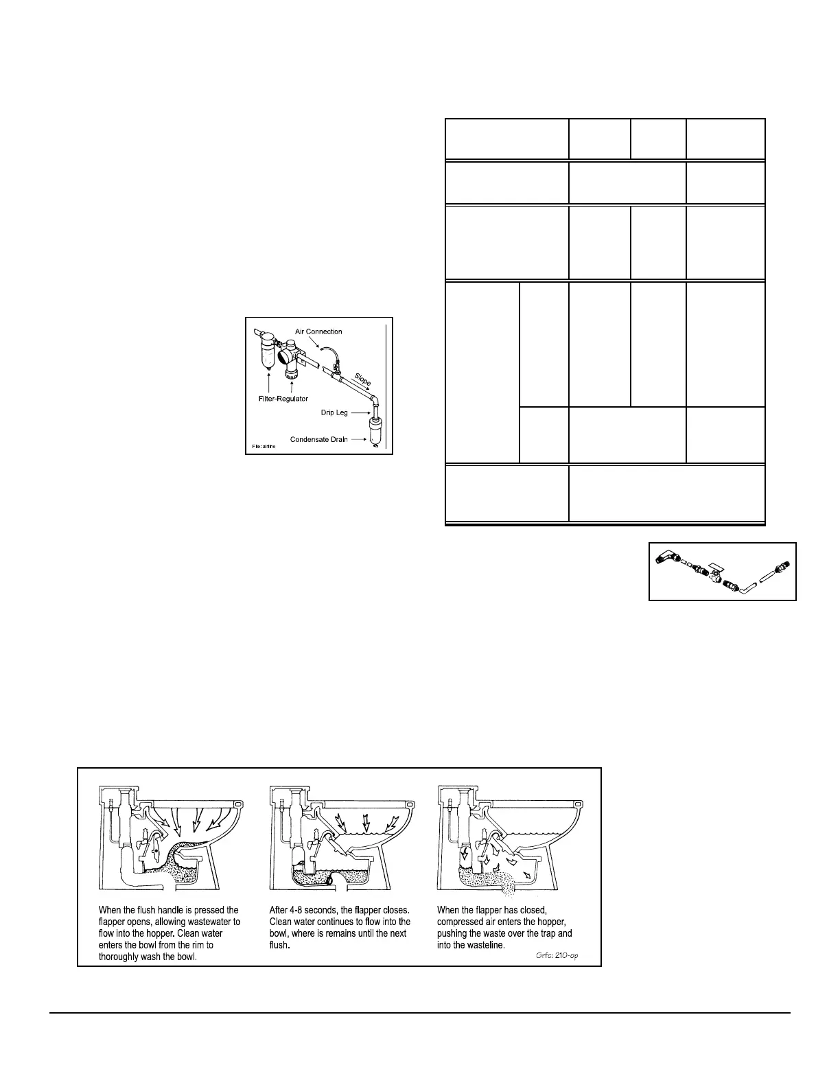
AIR SYSTEM
Filter-regulators are
available in a variety of
sizes and types. Their
purpose is to remove
water, oil and other
foreign matter from the air
line and to maintain a
constant pressure at the
toilet of 60-65 PSI. The following steps must be
observed to assure moisture will be removed from
the airline:
1. Drain air compressor receiver regularly. Most
water tends to accumulate at this point.
2. Install drip legs with condensate drains at all low
points in air piping.
3. Whenever possible, grade all airlines back to the
air receiver or drip leg assembly and drain
regularly.
4. The air supply to your Microflush Marine Head
must be taken from the top of the main or branch
air line.
AIR COMPRESSOR
Be certain compressor crankcase has proper oil
levels. Locate the compressor in a clean, dry, well
ventilated location. Size compressor according to
separate Air Compressor Specifications Sheet.
ITEM LF-210 LF-219
LF-310
LF-320
Air Line Connection Compression
1/4" 45
o
Flare Fitting
Water Line
Connection
1/2"
MIPS
Slip Joint
Nut
3/4" ID
Hose
Barb
1/2" FNPT
Fitting
Drain
Connection
Down
12"
(305mm)
on center-
line
2.25"
(57mm);
3.6"
(91mm)
off
center-
line
Not
Available
Rear
1-1/2" outlet, 3/4"
(19 mm) off
centerline
Centerline
Remote Valve
Assembly
Must be mounted so vacuum
breaker is located 6" above rim of
toilet bowl.
1 PRE-INSTALLATION
Following procedures apply
to all Microflush models
unless otherwise noted.
Remove your Marine Head
from box carefully.
Integral Models - Install toilet seat and flush
handle before mounting Microflush to floor.
Seat is not included with LF-210 and LF-219
models. Bolt caps and closet screws are
provided with LF-210 and LF-219 models.