wc_tx003683gb_FM10.fm
124
Mobile Generator
How to Connect Loads (600V)
12.2 Best Practices for Balancing Loads
Background
Three-phase (3Ø) loads are, by their nature, balanced. It is when single-phase
(1Ø) loads are combined with existing 3Ø loads that an unbalanced condition can
occur. Dedicated 1Ø loads may also be unbalanced if the loads are not equally
distributed between the legs (L1 and L3) of the generator.
The sensing wires of the generator’s voltage regulator are connected to L1 and L3.
Having the loads balanced between L1 and L3 allows the generator to provide
voltage that is more consistent with the voltage needs of the equipment connected
to it.
Note: When in the 600V mode, single phase power is not available.
1Ø Situations
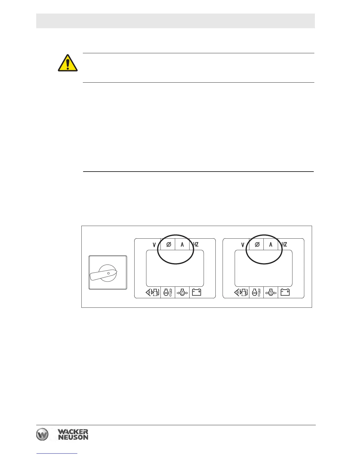
For 1Ø situations (voltage selector switch in the 208/240V position)
Unbalanced loads can be detected by observing the genset controller LCD panel. If
an unbalanced load condition exists, there will be a significant difference (over
10%) in both voltage and amperage between the legs.
Observe the amp draw on L1 and L3.
If an unbalanced load condition is detected, stop the engine and reconnect the
loads so that loads (amp draw) are more equally distributed between the legs (L1
and L3)—for example, if a heavy load and a light load are connected to L1, but only
a light load is connected to L3. Reconnect the loads so that the heavy load is
connected to L1, and the two lighter loads are connected to L3. Redistributing the
loads will equalize the voltage for each leg and allow for better performance from
the equipment connected to the generator.
Reconnect the loads as necessary to provide the most equal amp draw between
L1 and L3.
This procedure continues on the next page.
WARNING
Electric shock hazard. High voltage can cause serious injury or death.
► Connections must be made by a qualified electrician.
1Ø
120/240V
3Ø
277/480V
208/240V 3
Ø
3Ø
346/600V
120/139V 1
Ø
120 L1 12 60
100% 175 60
13
120 L3 12 60
100% 175 60
13
wc_gr011280
1Ø ZIG-ZAG
Observe L1 and L3