wc_tx003635gb_FM10.fm
53
Operation, Control, and Component Locations
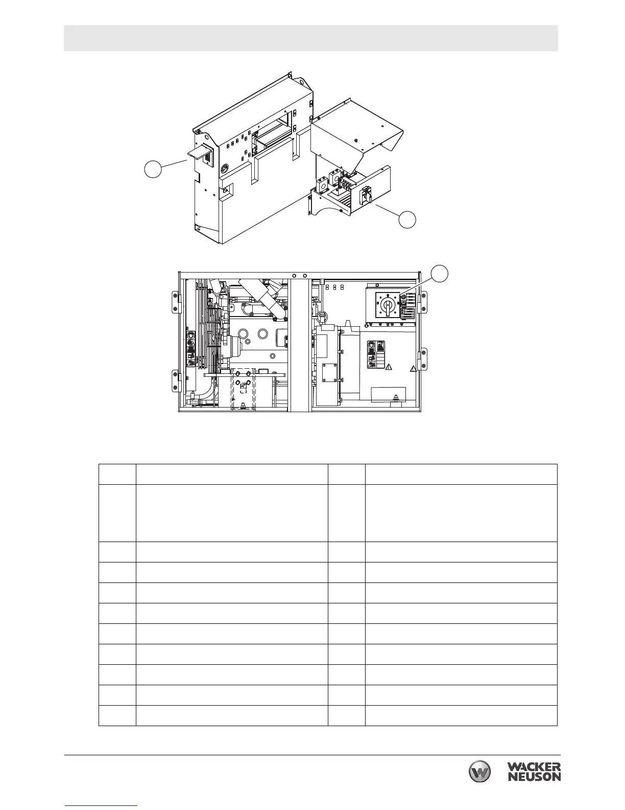
6.2 Control Panel Components
Ref. Description Ref. Description
a
Main circuit breaker
l
Twist-lock receptacle
(2) 240 VAC, 50A
optional:
(2)
240 VAC 20A, (1) 240 VAC 50A
b Voltage adjustment rheostat m GFI receptacle (120 VAC, 20A)
c Genset controller (Basler or Deep Sea) n Remote run terminal block
d Idle switch (high and low) (if equipped) o Emergency stop switch
e Ground connection point p Lug door interlock switch
f Pre-alarm/shutdown LED q Bond bar
g Engine start switch r Terminal lugs
h Hour meter s Voltage selector switch
j Circuit breaker (240V, 20A or 50A) t Fuse box
k Circuit breaker (120V, 20A) — —