wc_tx003634gb_FM10.fm
32
Label Meanings G 25
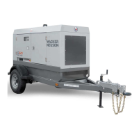
Y Operating the main circuit breaker supplies or
interrupts power to the customer connection lugs.
Z Neutral bonded to frame
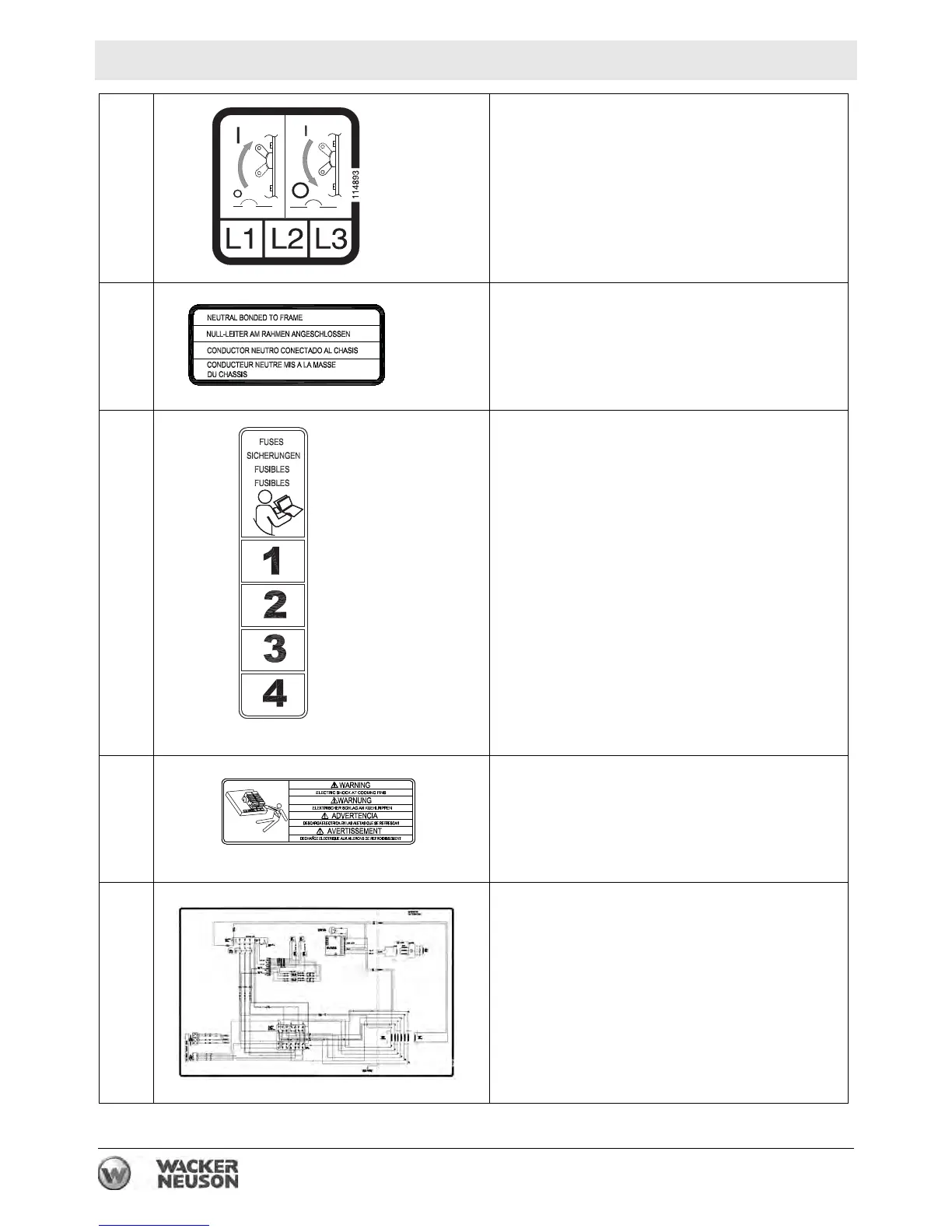
AA Fuses
Read the Operator’s Manual for machine
information.
BB WARNING
Electric shock at cooling fins.
CC Generator and receptacle wiring