ghi_tx001464gb_FM10.fm
61
HI400HD D / HD G Setting up the Burner
6.3 Setting up the Burner
Factory
settings
Background
The burner consists of several different components and subsystems. Each of
these components or subsystems must be operating correctly for the burner to
function properly.
Tools required
The following tools are required to adjust the burner:
■ High-quality combustion analyzer
■ Smoke spot tester
■ Fuel pressure test gauge
■ General hand tools
Mandates
■ Adjustments made shall be done so that the machine conforms to the
requirements of local, state, and federal codes and authorities.
■ Adjustments shall be made at the job site.
When
Adjust the burner:
■ Before operating the machine at elevations 305 m (1,000 ft) above or below the
location of where the last adjustments were made
■ Before starting at a new job site
■ After any burner maintenance or repair has been performed
■ If burner performance is in question
Procedure
Perform the procedure below to set up the burner.
1. Shut down the machine.
2. Set the burner electrodes.
(See topic Inspecting/Adjusting the Oil Burner Electrodes.)
3. Check the burner nozzle.
(See topic Checking/Changing the Burner Nozzle.)
4. Check and adjust the burner air damper if necessary.
(See topic Checking and Adjusting the Air Damper.)
5. Start the machine and the burner.
6. On D models only, check/set the fuel pressure.
(See topic Checking/Adjusting the Fuel Pressure.)
7. On G models only, check/set the gas pressure.
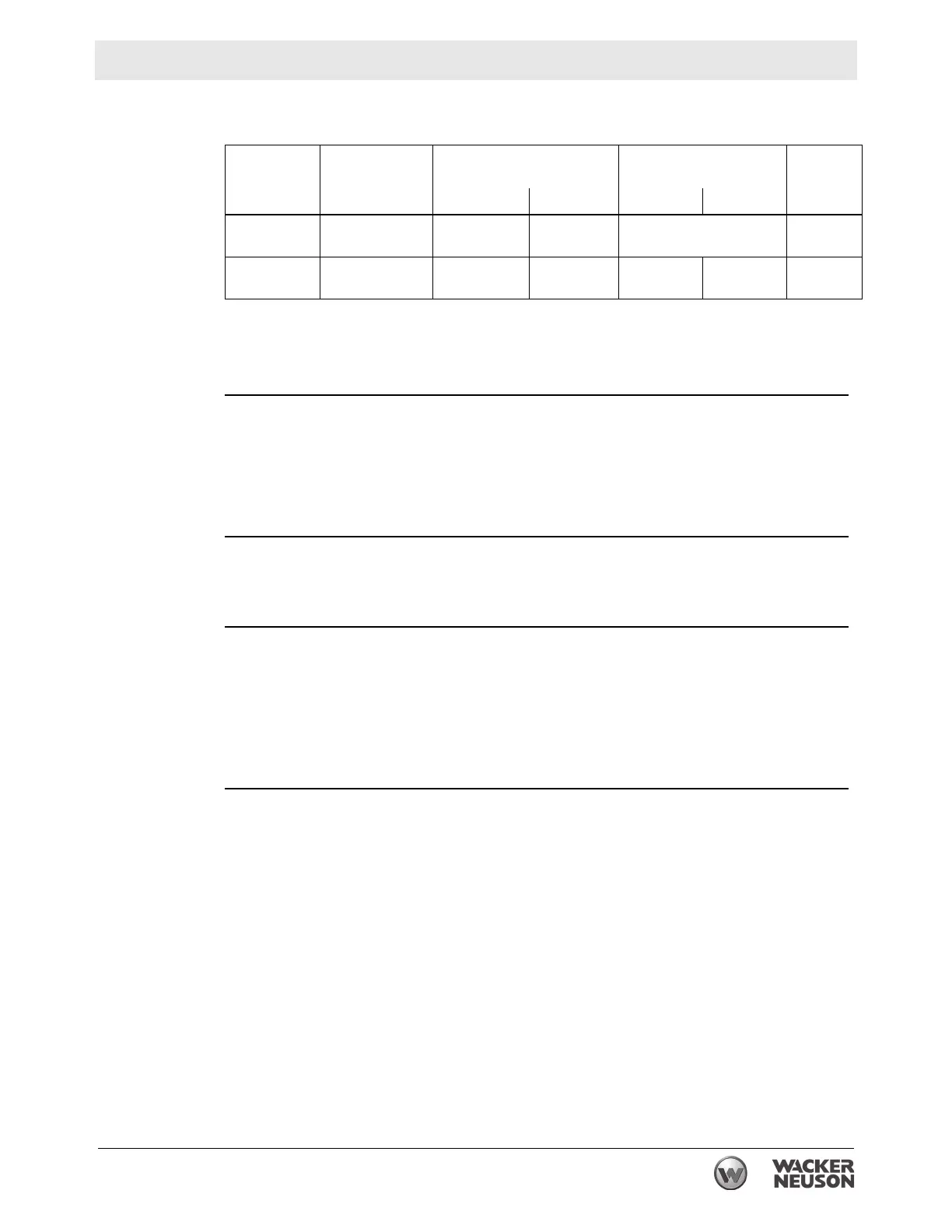
Machine Nozzle size Fuel pressure
Burner pressure
in WC
Air
damper
setting
psi bar NG LP
HI400 HD
D
2.00 (80W)
gph
Stage I: 160
Stage II: 217
Stage I: 11
Stage II: 15
—1.5
HI400 HD
G
3 x 2.8 mm
(12 X 0.11 in.)
——
6.40
(1600 Pa)
6.52
(1630 Pa)
3
 Loading...