F
18
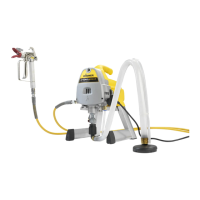
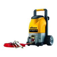
ProjectPro 213 ExtraGB
18
ProjectPro 213 Extra
Open the frame at the side closures (Fig. 1, Item 22) and fold it open.2.
Always lower the handle in the cover before opening the basic device cover (Fig. 1.
3.
Item16).
Open the closure (Fig. 1, item 17) and fold open the cover of the basic device. 4.
Unroll the power cable and slide the cable grommet into the provided recess (Fig. 4).5.
ATTENTION: Do not close the cover if the cable grommet is not positioned
correctly. The power cable could otherwise be damaged!
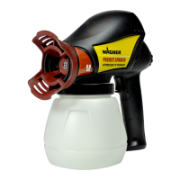
Remove the spray attachment from the deposition tray. Unscrew the container from 6.
the spray attachment.
Align the ascending tube. (Fig. 5) 7.
If the ascending tube is positioned correctly, the container contents can be sprayed
without almost any residue. When working on lying objects: Turn the ascending tube
forwards. (Fig. 5A)
Spraying work when working on overhead objects: Turn the ascending tube
rearwards. (Fig. 5B)
Place the container on a paper base and ll in the prepared coating material.
8.
Screw the container rmly onto the spray attachment.
Reclose the cover of the basic device with the lowered carry handle.9.
Open the Velcro fasteners (Fig. 1, Item 15) und unroll the air hose. Connect it to the 10.
air hose connection (Fig. 3).
Close the frame again11.
Connect the front part of the gun and the gun handle to each other. (Fig. 6)12.
Put the spray gun onto the gun holder (Fig. 1, Item 13).13.
Switch on the main switch at the device (Fig. 1, item 14).14.
Remove the spray gun from the gun holder and point it at the object to be coated. 15.
ATTENTION: It is advisable to test spray cardboard or a similar material
in order to determine the material and amount of air for an
optimal spray pattern.
Press the On/O switch at the gun handle (Fig. 7, item 2).16.
Three dierent spray jet settings can be chosen on the spray gun, depending on
the application and target object.
Selecting the Spray Setting
Fig. 8 A = horizontal at jet for horizontal surfaces
Fig. 8 B = vertical at jet for vertical surfaces
Fig. 8 C = circular jet for corners, edges and hard-to-reach surfaces
Adjusting the desired Spray Setting (Fig. 9)
With the union nut (1) slightly unscrewed, turn the air cap (2) to the desired spraysetting
position (arrow). Then tighten the union nut.
WARNING! Danger of injury! Never pull the trigger guard while adjusting
the air cap.