Do you have a question about the WAGNER ProSpray 3.29 and is the answer not in the manual?
Explains safety symbols used in the manual, detailing potential hazards.
Warns about high-pressure injection hazards and lists preventative measures.
General warnings about injury/damage and overall safety precautions.
Explains risks of electrostatic charging and necessary grounding.
Table showing recommended materials and object sizes for the sprayer.
Information on processable coating materials, viscosity, and filtering.
Explains the basic airless spraying process and its advantages.
Describes the technical construction and how the unit operates.
Provides detailed technical specifications for PS 3.29 and PS 3.31.
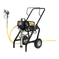
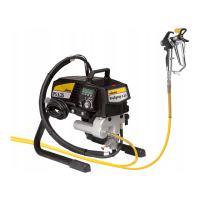
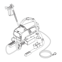
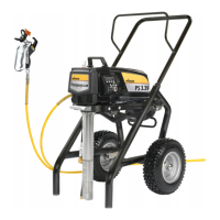
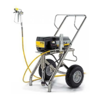
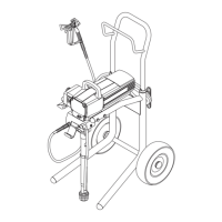
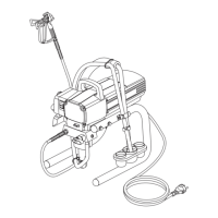
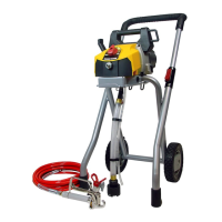
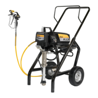
Illustrated diagram of the sprayer with numbered parts.
Instructions for moving and transporting the unit.
Guidance on securing the unit for transport in a vehicle.
Steps for connecting the hose, gun, and adding oil.
Details the settings and functions of the pressure control knob.
Procedure for flushing the unit with cleaning agent before first use.
Steps for preparing and starting the unit with coating material.
Key to a good paint job: even coating via constant speed and distance.
Keep the spray gun at right angles to the surface for uniform coverage.
Trigger gun after stroke starts, release before ending; overlap strokes by 30%.
Provides guidelines for safe handling, bending, and maintenance of the high-pressure hose.
Steps for safely interrupting operation and preparing for storage or cleaning.
Instructions for cleaning the exterior of the unit.
Steps for cleaning or replacing the suction filter.
Instructions for cleaning the airless spray gun and its intake filter.
Annual servicing recommendations by Wagner.
Inspection and replacement advice for the high-pressure hose.
Steps for replacing the relief valve.
Detailed instructions for servicing inlet and outlet valves.
Procedure for removing and replacing packings.
Electrical connection diagram for the sprayer.
Lists error messages from the DESC system and their meanings.
Guidance on selecting the appropriate spray tip for different applications.
Procedures for maintaining and cleaning spray tips.
Lists and details various accessories for the spray gun.
Comprehensive table of airless tips, applications, and specifications.
Continuation of the airless tip table with more applications.
Information about the TempSpray system for heating paint.
Details the Pump-Runner accessory for cleaning and preservation.
Illustrated diagram of spare parts for accessories.
List of spare parts for the sprayer with part numbers and descriptions.
Exploded view of the main assembly of the sprayer.
Detailed list of spare parts for the sprayer with part numbers.
Exploded view of the fluid section of the sprayer.
Detailed list of spare parts for the fluid section.
Exploded view of the drive assembly of the sprayer.
Detailed list of spare parts for the drive assembly.
Exploded view of the high-pressure filter assembly.
Detailed list of spare parts for the high-pressure filter.
Exploded view of the upright cart assembly.
Detailed list of spare parts for the upright cart assembly.
Defines the scope and coverage of the guarantee.
Outlines the guarantee duration and registration process.
Procedures for making guarantee claims.
Lists conditions under which the guarantee is not valid.
Additional legal and contractual regulations for the guarantee.
Continues the declaration of conformity in various languages.
Lists contact information for international sales and service locations.
| Type | Airless Paint Sprayer |
|---|---|
| Max Pressure | 3300 PSI |
| Hose Length | 15 m |
| Motor power | 0.33 HP |
| Voltage | 230 V |
| Frequency | 50 Hz |
| Power Source | Electric |
| Max. tip size | 0.021 inches |