36
PXM
P_02583
1
2
3
4
P_02622
OPERATING AND ASSEMBLY MANUAL
VERSION 08/2015 ORDER NUMBER DOC2350372
10. Horizontally align the PXM using the leveling feet on the frame.
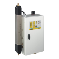
11. Align the intake tubes so that they meet centrally in the blowout nozzles.
To do this, rst align the PXM with the leveling feet.
If necessary, loosen the four screws from the mounting plate of the blowout nozzles
and bring the nozzles into position.
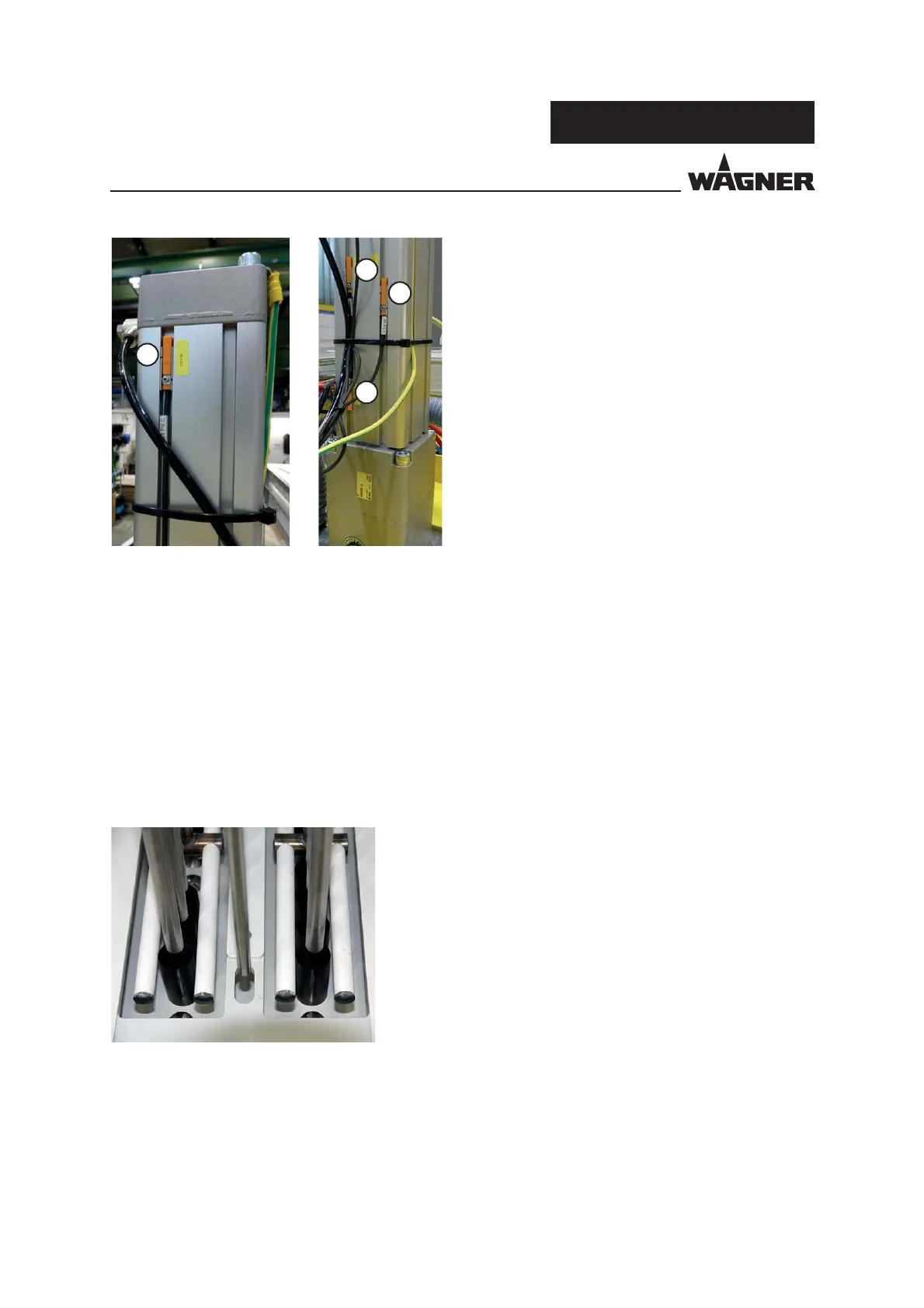
Limit switch 1: Top = Cylinder moved all the way up.
Setting: Uppermost cylinder position
Limit switch 2: Warning = Advance warning that the powder level will be reached soon.
Setting: 2 cm above limit switch 3
Limit switch 3: Minimum = Powder level minimum; cylinder does not move further
downwards.
Setting: Fluid tubes 1 cm from the uid oor of the tank; use tank
Order No. 3304505.
Limit switch 4: Cleaning = Intake tubes dip into blowout nozzles.
Setting: Intake tube 1 cm in blowout nozzle