4 Table of Contents WAGO-I/O-SYSTEM 750 XTR
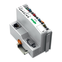
750-352/040-000 FC ETHERNET G3 XTR
Manual
Version 1.3.0
4 Device Description .................................................................................. 45
4.1 View ..................................................................................................... 47
4.2 Connectors ........................................................................................... 49
4.2.1 Device Supply .................................................................................. 49
4.2.2 Fieldbus Connection ........................................................................ 50
4.3 Display Elements .................................................................................. 51
4.4 Operating Elements .............................................................................. 52
4.4.1 Service Interface .............................................................................. 52
4.4.2 Address Selection Switch ................................................................. 53
4.5 Technical Data ..................................................................................... 54
4.5.1 Device Data ..................................................................................... 54
4.5.2 System Data .................................................................................... 54
4.5.3 Supply .............................................................................................. 55
4.5.4 Fieldbus MODBUS/TCP ................................................................... 55
4.5.5 Accessories ..................................................................................... 56
4.5.6 Connection Technology ................................................................... 56
4.5.7 Mechanical Conditions ..................................................................... 56
4.5.8 Climatic Environmental Conditions ................................................... 56
4.6 Approvals ............................................................................................. 57
4.7 Standards and Guidelines .................................................................... 58
5 Mounting .................................................................................................. 65
5.1 Installation Position ............................................................................... 65
5.2 Overall Configuration ............................................................................ 67
5.3 Mounting onto Carrier Rail .................................................................... 68
5.3.1 Carrier Rail Properties ...................................................................... 68
5.3.2 WAGO DIN Rails ............................................................................. 69
5.4 Spacing ................................................................................................ 69
5.5 Mounting Sequence .............................................................................. 70
5.6 Inserting and Removing Devices .......................................................... 71
5.6.1 Inserting the Fieldbus Coupler/Controller ......................................... 71
5.6.2 Removing the Fieldbus Coupler/Controller ....................................... 72
5.6.3 Inserting the I/O Module ................................................................... 72
5.6.4 Removing the I/O Module ................................................................ 73
6 Connect Devices ..................................................................................... 74
6.1 Data Contacts/Local Bus ...................................................................... 74
6.2 Power Contacts/Field Supply ................................................................ 75
6.3 Connecting a Conductor to the CAGE CLAMP
®
................................... 76
7 Function Description .............................................................................. 77
7.1 Operating System ................................................................................. 77
7.2 Process Data Architecture .................................................................... 78
7.2.1 Basic Structure................................................................................. 78
7.2.2 Process Data EtherNet/IP ................................................................ 79
7.3 Data Exchange ..................................................................................... 80
7.3.1 Addressing ....................................................................................... 81
7.3.1.1 Addressing of I/O Modules .......................................................... 81
7.3.2 Data Exchange between MODBUS/TCP Master and I/O Modules ... 82
7.3.3 Data Exchange between EtherNet/IP Master and I/O Modules ........ 84

 Loading...