Operating Instructions
42
4. Slow the engine to idle, put throttle in IDLE posi-
tion; turn the ignition switch OFF.
WARNING
Remove the key from the ignition switch
when leaving the mower unattended. This
will prevent children and inexperienced
operators from starting the engine.
5. Engage the parking brake. Also, engaging the
parking brake is recommended when stopping
or parking the machine in a conned space with
little tolerance for movement.
IMPORTANT: The hydrostatic transmissions
lock to prevent the mower from rolling freely
with the engine stopped. However, if the
mower is parked on a slope, it is necessary to
ENGAGE the parking BRAKE to prevent
the mower from creeping. This is due to a small
amount of slip page in the hydrostatic transmis-
sions, especially when transmission uid is
warm.
WARNING
In case either of the transmission drive
belts break during operation, and if the
machine is on a slope, the machine will
freewheel down the slope. To maintain
control, immediately (1) Release the
steering levers and simultaneously (2)
Move the FSC to the NEUTRAL-PARK
position. When the machine is stopped or
moving slowly, engage the parking brake.
NOTE: The emergency stop procedure is exactly
the same procedure as used to normally stop and
park the machine.
ADJUSTING CUTTING HEIGHT
WARNING
The engine must be stopped before ad-
justing cutting height. Disengage the blade
clutch (PTO), stop the engine, and remove
the ignition key. Wait for all move ment to
stop before getting off the seat.
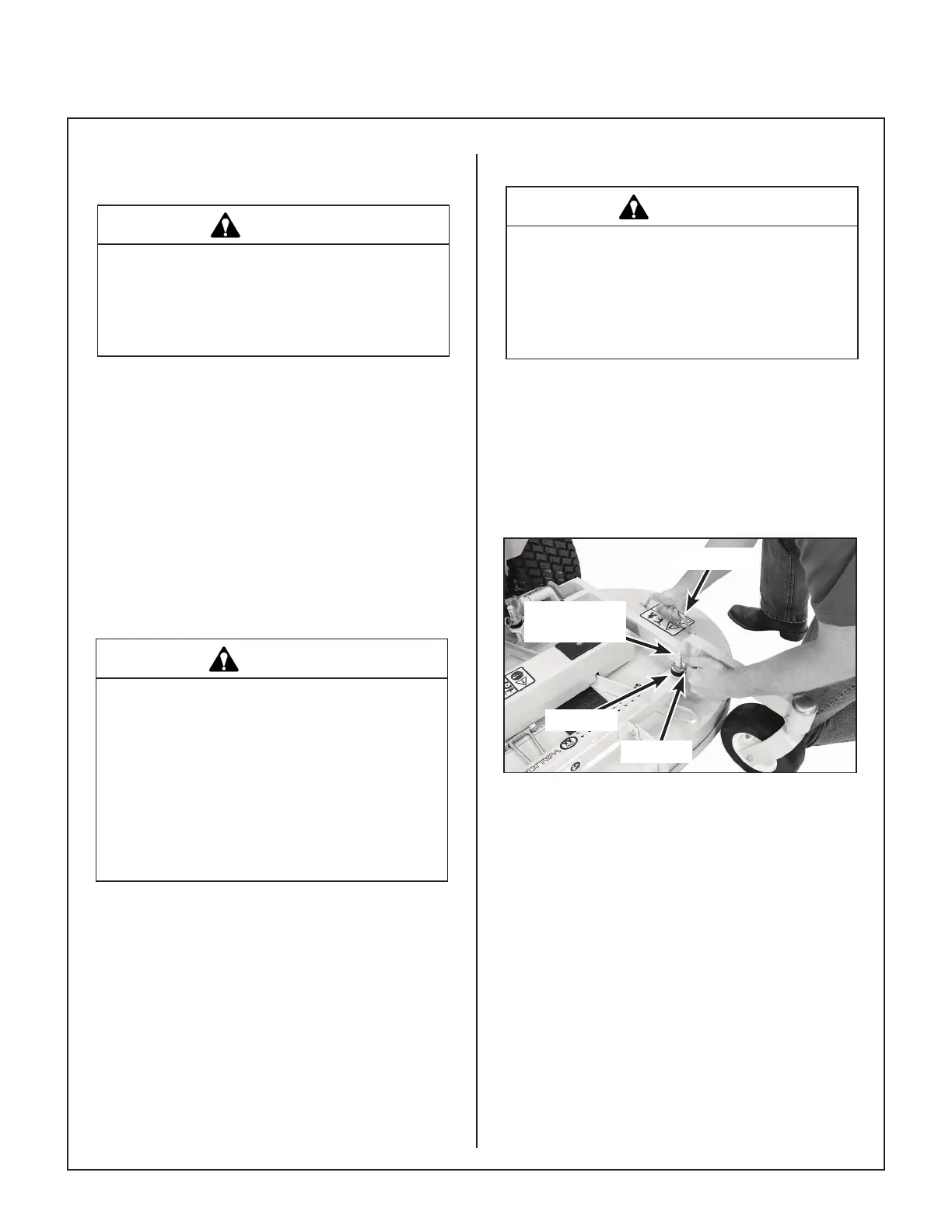
Cutting height is adjusted by positioning the four (4)
re tainer hitch pins in a series of six vertical holes on
the deck support pins. Lift handles have been pro-
vided on each end of the deck to assist in raising the
deck while positioning the hitch pins. Cutting heights
range from 1.5 in. (38 mm) [top holes] to 4 in.
(102 mm) [bottom holes] in 1/2 in. (13 mm) incre-
ments.
Lift Handle
Deck Support
Pin
Hitch Pin
Washer
Cutting Height Adjustment
TRANSMISSION LOCKOUT
IMPORTANT: DO NOT TOW this mower with the
transmission lockout engaged. Towing can produce
excessive internal pressure and damage the trans-
mission.
To move the mower with the engine NOT running
(dead battery, maintenance, etc.), the hydrostatic
transmissions are unlocked (released).
1. Raise the body.
2. Lift the transmission lockout lever on both the
RH and LH transmissions and secure into place
with the locking cam.