WBPS-IM-001-EN
4/9
2. Startup
Once system is energized, the Master communicates with the Slaves.
Slaves shows below LED status color:
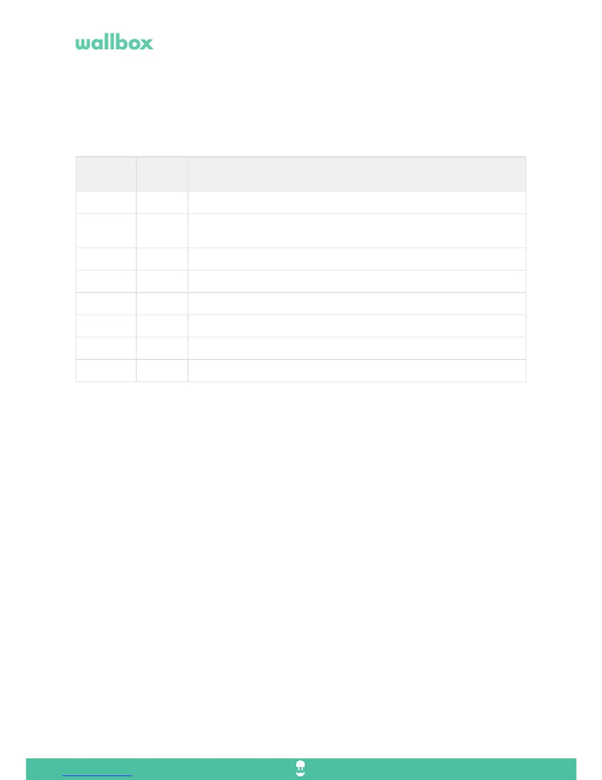
LED
Color
Blinkin
g
Function
Yellow slow Waiting for address from the master.
Green slow Successful communication with the master and waiting on current assignment
from the master.
Green
Connected waiting for car demand.
Turquoise quick Lost connection. (waiting for car demand)
Blue slow Charging.
Blue quick Lost connection. (charging)
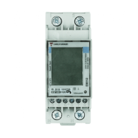
3. Connection scheme
Communication between chargers is CAN bus daisy chain.
All the chargers must be connected on series.
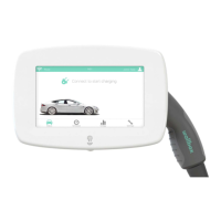
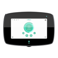
Commander is Master – Needs to be set on the internal selector.
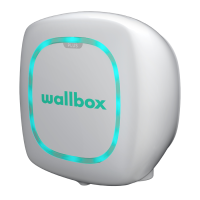
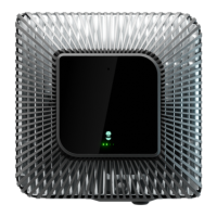
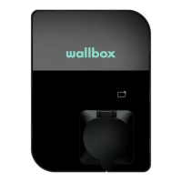
Pulsar is Slave – Needs to be set on the internal selector
Version 1 on Power Sharing requires to install the Pulsar termination (Pulsar identified as end of line)
It is mandatory that the first charger is a Commander and the last a Pulsar identified as a “Pulsar termination”.
Cable Specs: 2 wires twisted pair and shielded. (UTP Cat 5)
Cable Distance: 300m