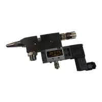
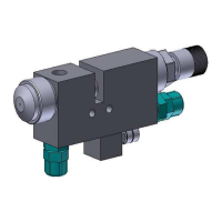
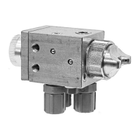
Assembly Instructions – Full-Jet Valve VMS-02
Walther Systemtechnik GmbH – D 76726 Germersheim
Telefon: +49 (0)7274-7022-0 Telefax: +49 (0)7274-7022-91
http://www.walther-2000.de – info@walther-2000.de
7 Maintenance and Repair
7.1 General Information
CAUTION
Before starting any maintenance or repair work, ensure that all air-operated tools are
depressurized and disconnected from the air supply.
Before opening the spray valve it must be disconnected from the air and fluid supply.
Otherwise, ejected components can cause injuries.
The full jet valves of the VMS-02 series are high-quality precision devices which will not fail if treated
correctly and will operate almost maintenance-free. Always keep clean and observe minimum instructions to
maintain a long life of the valve. Always use clean and filtered material only. The control air must also be
clean and should be slightly oiled, if necessary. Maintenance also depends on the individual operating
conditions and the type of media used.
7.2 Cleaning
IMPORTANT
Only use soft brushes for outside cleaning of the nozzle tips. Never use metal tools with
sharp edges.
Wash equipment thoroughly after use to remove residues and dirt, especially if needle (5) or sealing screw
(4) or nozzle (1) has to be exchanged.
7.3 Replacing Needle (Pos. 5.0) and Nozzle (Pos. 1.0)
CAUTION
First depressurize all connections.
Completely unscrew raster needle lock (pos. 7.0). Unscrew nozzle (pos. 1.0). Take out the needle spring
(pos. 6.0) and carefully press out needle (pos. 5.0) from the nozzle side. Grease new parts slightly and
reassemble them in reverse order. We do not recommend reusing old needles. Piercing of slightly dirty
needles through the form gasket (pos. 3.3) can cause leakages.
7.4 Replacing the Sealing Screw (Pos. 4.0)
Completely unscrew raster needle lock (pos. 7.0) and nozzle (pos. 1.0). Carefully push out the needle (pos.
5.0) towards the nozzle end. Then unscrew the sealing screw (pos. 4.0) from the thread with a screwdriver.
Since the outer O-ring (pos. 3.1) prevents the sealing screw from falling through the mounting thread of the
valve body (pos. 2.0), it is necessary to push the sealing screw together with O-ring (3.1) carefully back-
wards through the thread using a thin strip of metal (0.5 – 1.0 mm) which you push between the recess in the
body and flat in front of the front end of the sealing screw. You can then take the sealing screw out of the
enclosure.